
Light-control electric toy circuit

The described circuit employs a phototube as a light sensor, which is sensitive to the illumination provided by the flashlight. When light falls on the phototube, it generates a small current that is fed into the CMOS logic circuit. The CMOS circuit is designed to operate with low power consumption, making it suitable for battery operation.
The output of the CMOS circuit controls a transistor switch, which in turn drives the motor. The choice of the transistor is crucial; for small motors, the 2N2222A is typically sufficient due to its ability to handle moderate current and voltage levels. However, for larger motors that require higher current, a power transistor such as the TIP120 or similar should be employed to ensure reliable operation without overheating.
Furthermore, the implementation of a baffle in front of the flashlight lens serves to focus the light more effectively onto the phototube, enhancing the sensitivity and reliability of the circuit. This adjustment is particularly important when using high-intensity flashlights, as excessive light can lead to false triggering of the circuit.
In summary, this circuit design integrates a phototube, a CMOS logic circuit, and a transistor switch to create a responsive control system for model trains and electric toys, allowing for efficient operation powered by a battery source while ensuring adaptability for various motor sizes.The light of flashlight aims at phototube, then CMOS logic circuit which adopts battery as power supply will occur switch action to turn on/off the motor of model train or other electric toys. To most small motor, the transistor can use 2N2222A; but the larger motors need power transistor. When using highlightflashlight, to add a baffle to lens to limit th.. 🔗 External reference
Related Circuits

A digital stopwatch or digital timer circuit schematic is constructed using the timer IC LM555 and the 4-digit counter IC MM74C926, which is paired with a multiplexed 7-segment LED display. The digital stopwatch circuit utilizes the LM555 timer IC configured...

JBD3-10 leakage protection circuit The JBD3-10 leakage protection circuit is designed to detect and mitigate leakage currents in electrical systems, enhancing safety and preventing potential hazards. This circuit employs a differential current transformer that continuously monitors the current flowing through...

A circuit utilizing a single analog multiplier and five precision resistors can produce an output voltage (Ko) that represents a second-order polynomial. This circuit implements the quadratic function. The input terminals of IC1 are configured to create a positive...
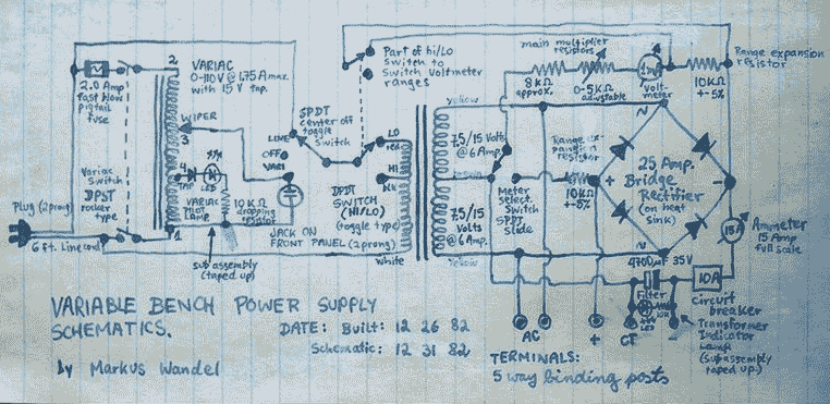
This power supply is able to deliver adjustable center-tapped DC from 0 to about 30 volts, as well as AC directly from the Variac and from the main transformer before the rectifier. What's primitive by today's standard is that...

The following circuit illustrates the AD8531 integrated circuit used for the automatic control of LCD panel backlighting. Features include the ability to compensate for aging effects and other functionalities. The AD8531 is a precision operational amplifier known for its low...
This is a 25-watt basic power amplifier designed for ease of construction at a reasonable cost. It outperforms the standard STK module amplifiers commonly found in mass-market stereo receivers today. The design was initiated to create a 25-watt amplifier...