
Second-Order Polynomial Generator Circuit

The circuit design revolves around the use of an analog multiplier, which serves as the core component for generating the quadratic output. The analog multiplier's functionality allows it to multiply two input voltages, effectively enabling the creation of the square term necessary for the second-order polynomial. The precision resistors play a crucial role in defining the coefficients of the polynomial, ensuring accurate scaling and adjustment of the output voltage.
The input signal, represented by Vr, is processed through a voltage-divider network composed of resistors R3 and R4. This network is essential for managing the input signal's amplitude and adjusting the coefficient (c) associated with the square term. By altering the resistor values, the attenuation can be finely tuned, allowing for precise control over the polynomial's characteristics.
In addition to the square term, the circuit includes a passive adder formed by resistors R1, R2, and R0. This configuration connects to the internal summing circuit of the analog multiplier, enabling the generation of the remaining two polynomial terms: the linear coefficient (b) and the constant offset term (a). The passive adder effectively combines these terms, ensuring that the output voltage accurately reflects the desired second-order polynomial.
Overall, this circuit provides a versatile and precise means of generating second-order polynomial outputs, utilizing a combination of an analog multiplier and carefully selected resistors to achieve the desired electrical characteristics. The design is well-suited for applications requiring polynomial signal generation and can be adapted for various input signal conditions by adjusting the resistor values accordingly. By using a circuit built with a single analog multiplier and five precision resistors, an output voltage (Ko) can be made to create a second- order polynomial. The circuit implements the quadratic shown. The input terminals of IC1 are connected to create a positive square term and present the Vr signal to the output with a 1-10-V scale factor.
Incorporating the voltage-divider network (resistors R3 and R4) in the input signal path provides additional attenuation adjustment for the coefficient (c) of the square term in the quadratic. Then, the passive adder (resistors Rl, R2, and Ro) is wired to ICl`s internal summing circuit to generate the polynomial`s other two terms; the offset term (a) and the linear coefficient (b).
Related Circuits
This circuit functions as a camera switch, allowing multiple cameras to be connected to a single monitor. It can operate in both manual and automatic modes. In automatic mode, the circuit utilizes a 555 astable multivibrator to generate a...
This is an intercom circuit that utilizes the LM380 as the audio amplifier and two transistors for the microphone preamplifier. The sound quality is sufficiently good while maintaining a low construction cost. The circuit comprises two identical intercom units,...
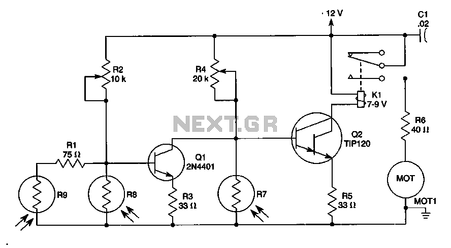
The sun trucker employs three photoresistors, R7, R8, and R9, to enable the circuit to track the sun during daylight hours while ceasing operation at night. Additionally, the circuit can be duplicated to achieve movement along four axes by...
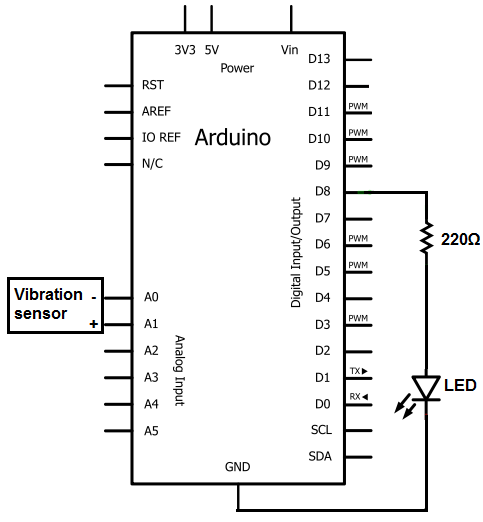
The sensors consist of a thin strip of piezoelectric material with a rivet at one end acting as a weight. When vibration occurs, the weight moves, stressing the piezo material, which generates a spike in voltage that can reach...
A unit that is often very useful for isolating two stages in sound circuits. This circuit incorporates an amplification unit with a gain of X1. It employs only local negative feedback rather than total negative feedback, resulting in very...
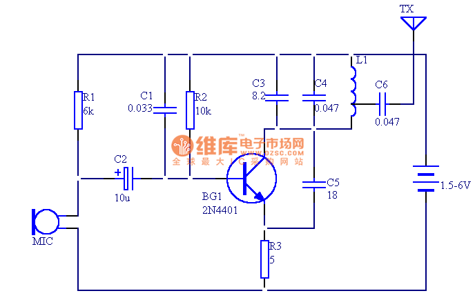
The circuit presented in this document utilizes 12 components to create a compact wireless FM microphone that operates with a stable frequency. The effective transmission range is approximately 30 meters, extending to over 100 meters when powered by a...