
Light control system of traffic of double mode of infrared remote-control on the basis of 89C52 one-chip computer

For illustrative purposes, consider two main roads running north-south that intersect at a crossroad, with four designated pedestrian pathways labeled A, B, C, and D. The operational conditions of the pilot lights at the intersection can be described as follows: when the danger light is active, vehicles are prohibited from passing through while pedestrians may cross at pathway D. Simultaneously, the north-south direction displays a green light, allowing vehicles to proceed while pedestrians must wait at pathway C for 60 seconds. The yellow light flashes for 5 seconds, alerting both vehicles and pedestrians of the imminent change to red. When the green light is active for vehicles, the danger light prevents pedestrian movement at pathway D, while pathway C remains open for crossing. The timing for pedestrian safety is also set at 60 seconds. This alternating system ensures orderly vehicle movement and safe pedestrian crossings.
The design primarily utilizes the 89C52 microcontroller, which serves as the main control unit coordinating the operation of other modules, including the traffic light display module, infrared receiver module, nixie tube, and key set. The key set and infrared receiver module facilitate the switching between operational modes: normal mode and peak mode. In normal mode, the danger light duration is set to 60 seconds, while in peak mode, it is reduced to 40 seconds. The traffic light display module indicates the status of each roadway, while the nixie tube shows the remaining time for the current traffic light cycle, helping pedestrians determine whether they have sufficient time to cross safely. The main block diagram of this system illustrates the interconnections between these components.
In recent years, the rapid economic development has led to a continual increase in vehicle numbers within urban areas, resulting in traffic congestion and a rise in traffic accidents. Effective traffic light control systems are crucial for managing these challenges and ensuring road safety.A steady, flexible, convenient traffic light control system to have necessity and realizability. But a lot of traffic lights are switched over according to a time interval in actual life. And the traffic lights can be according to changing the switching time of traffic light in peak period at ordinary times or on and off duty in this design, if the intersection of danger light and change-over time set up as 40 seconds, set up as 60 seconds at ordinary times peak period on and off duty. Can relieve in commuter time effectively so, because danger light is set up too long, phenomenon of making a dash across the red light in order to make up for lost time. Meanwhile, relieve the traffic jam phenomenon effectively. In 1968, the United Nations the road traffic and marking signal protocol of the road made the regulation to the meaning of various indicator lights: The green light is on to allow to pass through; The danger light is on, No thoroughfare; Yellow lamp on, brief people on, pay attention to red, state of green light namely switch.
For convenience prove, suppose the things now, two main roads running N-S intersect at a crossroad. At the same time, in order to guarantee pedestrians are safe, set up A, B, C, D four pedestrain ways. As shown in Fig. 1. Pilot lamp working condition proves at the crossing: It is danger light in the things one, this vehicle forbids passing through, B at this moment, the pedestrian can pass the road on D pedestrain way; The north and south one is a green light at the same time, this vehicle passes, A at this moment, the pedestrian forbids passing through on C pedestrain way, time is 60 seconds.
Yellow lamp glimmer 5 second, it warns vehicles and pedestrians to be red, state of green light namely switch. It is green lights in the things one, this vehicle passes through, B at this moment, the pedestrian forbids passing the road on D pedestrain way; The north and south one is danger light at the same time, this vehicle forbids passing, A at this moment, the pedestrian is passable on C pedestrain way, time is 60 seconds.
The circulation according to this, can guide the vehicle to go in order, the pedestrian passes the road safely. Design mainly by the intersection of 89C52 and one-chip computer, the intersection of traffic and the intersection of light and display module, infrared to receive module, nixie tube, key set, etc.
, make up originally. 89C52 one-chip computer is a systematic main control unit, control other module to coordinate the work; Key set and infrared to receive the module to come and switch over the systematic work pattern: Normal mode or peak mode on and off duty. Namely under the normal mode, the time that the danger light sets up is 60 seconds; Under the peak mode on and off duty, the time that the danger light sets up is 40 seconds.
The light display module of the traffic is used to show the passing through of every way vehicle, the nixie tube, in order to reveal the last switching time of traffic light of traffic, the pedestrian whether the judgement has enough time to cross the road according to this, walk or stop. Its main block diagram is shown as in Fig. 2. In recent years, with the fast development of economy, the vehicle is increasing constantly in the city.
Therefore cause the traffic jam, clogging, a series of question that the traffic accident takes place frequently, etc. The traffic light is the important traffic command system of t 🔗 External reference
Related Circuits
Just point this small device at the TV and the remote gets jammed. The circuit is self-explanatory. 555 is wired as an astable multivibrator for a frequency of nearly 38 kHz. This is the frequency at which most of...
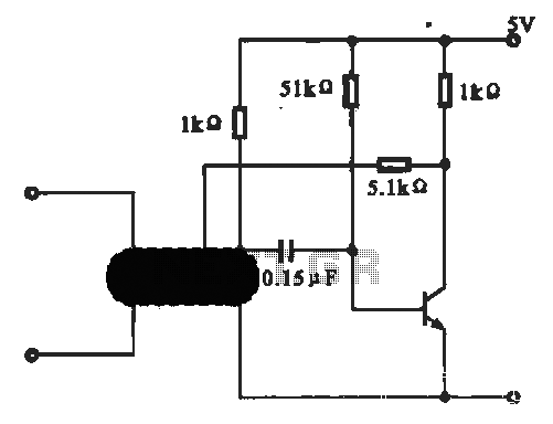
This circuit illustrates an oscillator that is controlled by an optocoupler, utilizing photoelectric coupling to drive a transistor. The oscillator circuit described operates by employing an optocoupler to provide electrical isolation between its input and output stages while allowing control...
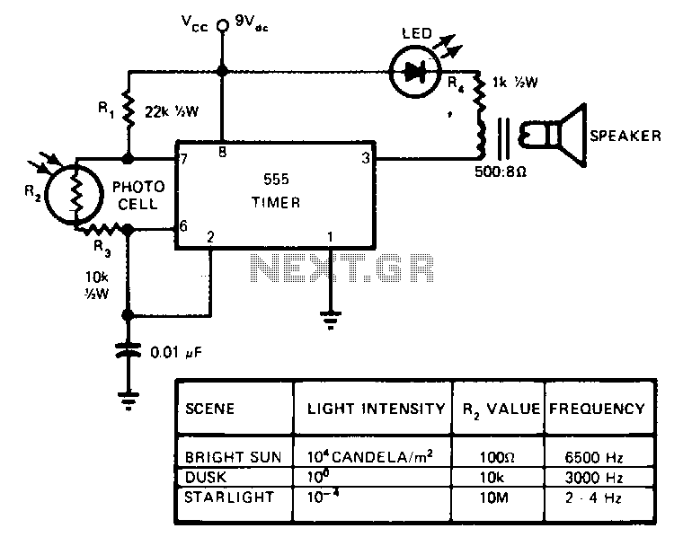
This circuit's frequency of oscillation increases directly with light intensity. The greater the light intensity, the higher the frequency of the oscillator. The 555 timer operates in the astable oscillator mode where frequency and duty cycle are controlled by...
A radio remote control system utilizing DTMF (Dual-Tone Multi-Frequency) technology is presented. This circuit allows for the control of various electrical appliances through radio frequency signals. The described radio remote control system employs DTMF tones, which are generated by a...
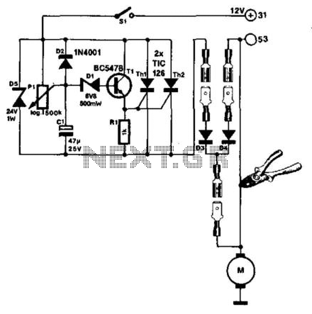
The windshield wiper interval circuit described here is compact and notable for utilizing two thyristors instead of a relay. It features only two connections and operates smoothly, even with multistage wiper circuits. The wire connecting the wiper motor to...
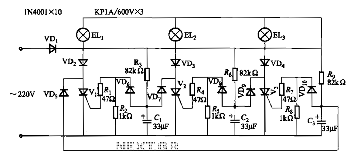
The circuit operates with a 220V mains supply through a diode (VDi) configured as a half-wave rectifier. Capacitors C1 to C3 are charged, and due to the lack of full synchronization in the charging process, a pilot thyristor is...