
Windshield Wiper Interval Controller

The windshield wiper interval circuit is designed to provide controlled operation of the wiper motor through a time-based interval system, enhancing the functionality of vehicle wipers. The circuit operates by utilizing two thyristors, which serve as electronic switches, replacing traditional mechanical relays. This design minimizes space requirements and improves reliability.
The operation begins with closing the interval switch (SI), which initiates the charging of capacitor (CI) through the resistor (PI) and the wiper motor. The time constant for the charging is determined by the values of PI and CI, allowing the user to set the desired interval for the wiper operation. Once the voltage across CI reaches a certain threshold, transistor (T1) is activated, which sends a triggering pulse to the thyristors, enabling them to conduct.
Upon the thyristors conducting, the wiper motor is powered through diode (D3), causing the wipers to start moving. During this motion, capacitor (CI) discharges through diode (D2) and the thyristors, providing the necessary current to maintain the operation of the wiper motor.
As the wipers complete their cycle, the wiper stop switch activates, connecting terminal 53 to the +12-V supply. This action energizes the wiper motor through diode (D4) while simultaneously causing the thyristors to turn off. The turn-off condition is achieved because the combined voltage drop across diode (D3) and the thyristors becomes greater than the voltage across diode (D4), effectively interrupting the current flow through the thyristors.
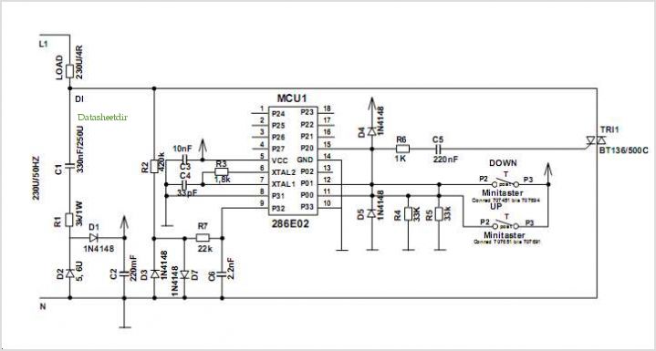
Once the wipers reach the end of their travel, the stop switch reconnects terminal 53 to ground, allowing capacitor (CI) to recharge, preparing the system for the next interval operation. This compact and efficient design ensures reliable wiper operation across various vehicle configurations, making it suitable for modern automotive applications. The windshield wiper interval circuit presented here is very compact and is noteworthy for its use of two thyristors, instead of a relay. It has only two connections and operates without any problems-even in conjunction with multistage wiper circuits. The connecting wire between the wiper motor and terminal 53 is cut and new connections are made (as shown in the diagram).
When the interval switch, SI, is closed, capacitor CI charges via PI and the wiper motor. After a time set with PI, transistor T1 switches on and triggers the thyristors. The wiper motor is then energized via the thyristors and D3 and sets the wipers into motion. At the same time, CI discharges via D2 and the thyristors. After a short time, the wiper stop switch connects terminal 53 to the +12-V line so that the wiper motor is energized via D4. The thyristors are switched off because the voltage drop across D3 plus Thl/Th2 is then greater than that across D4.
When the wipers reach the end of their travel again, the stop switch connects terminal 53 to ground and enables CI to charge again.
Related Circuits
The heart of the PWM Fan Controller is a PIC 12F675 microcontroller. This microcontroller is reading the analog output of a LM35 temperature sensor using a ADC (analog to digital converter). The resulting digital value is converted to a...
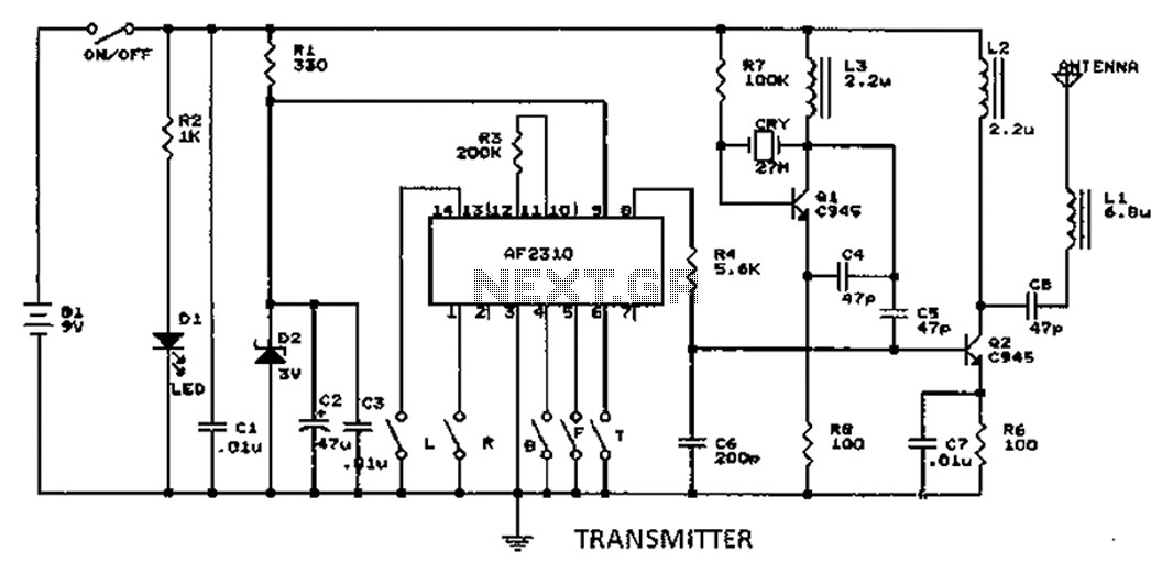
A radio control circuit designed for controlling small motors, similar to a car radio remote control toy, offers seven functions: forward, backward, left, right, left behind, right behind, and stop. The circuit requires a 27.9 megahertz frequency and a...

Efforts were made to minimize the number of wire jumpers on this board, but space constraints arose due to the integration of the microcontroller and motor driver on a single board. The design would have been cleaner without the...
Introduction The ignition timing lights commonly used range from simple neon to complex units. Neon timing lights have a drawback due to their low light output, necessitating operation in subdued lighting. This presents a safety hazard, as users tend...
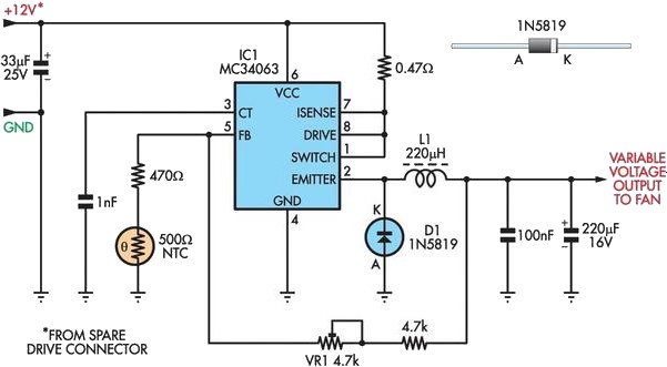
A partial solution to reducing noise from PCs can be achieved by lowering the speed of internal cooling fans. Low-cost fan speed controllers are available, but they often utilize inefficient, heat-generating linear regulators and lack a temperature feedback mechanism....
Currently using the PIC24FJ128GA010, there is a plan to utilize an Input/Output port to connect a 4.2 V LiPo battery and monitor the voltage to ensure it does not drop below 3.7 V. It is advised to avoid digital...