
Light-Dependent Sensor For Multiple Inputs Circuit

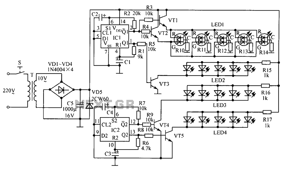
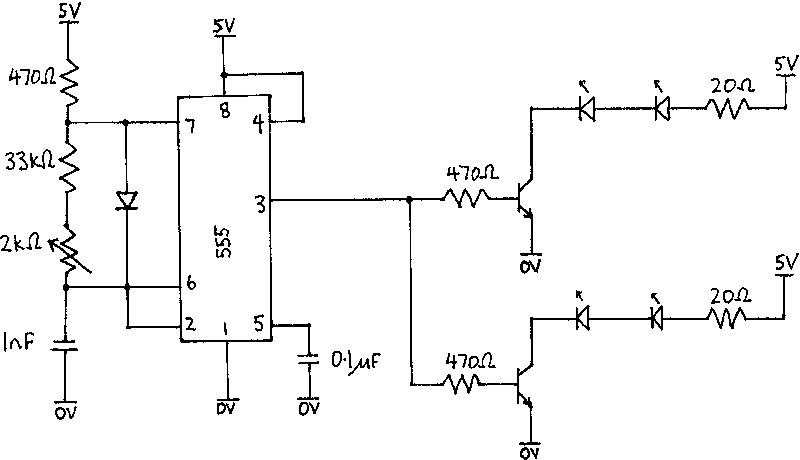
The circuit typically consists of an LDR connected in a voltage divider configuration with a fixed resistor. The output voltage from this divider is fed into a comparator or microcontroller input. When the ambient light level is above a certain threshold, the voltage remains below the reference level set at the comparator. In this state, the output remains low, and the alarm remains silent.
When the light is interrupted—such as by an object passing in front of the sensor—the resistance of the LDR increases, causing the voltage at the comparator input to rise above the reference level. This change triggers the output of the comparator to switch states, activating the alarm.
To enhance the circuit's reliability, hysteresis can be introduced by adding a feedback resistor from the output of the comparator back to the non-inverting input. This prevents the alarm from chattering due to minor fluctuations in light levels. The alarm can be a simple piezo buzzer or a more complex sound module, depending on the application requirements. Additionally, a power supply circuit may be included to ensure stable operation, along with a reset mechanism to allow for manual or automatic reset of the alarm after it has been triggered.
Overall, this light-dependent sensor circuit is effective for applications such as security systems, where detecting the interruption of light can indicate unauthorized access or movement in a designated area. This light-dependent sensor uses LDRs to detect the presence or absence of light. As long as the light source striking the LDRs remains constant, the alarm does not sound. But when the light is interrupted, the alarm is triggered.
Related Circuits

This is a buffer circuit for the TMP01 temperature sensor. The output of this sensor is a low impedance DC output voltage with a 5 mV/K temperature coefficient. The buffer circuit designed for the TMP01 temperature sensor serves to isolate...
The electronic components designed by conventional electronic bonsai create a sparkling and brilliant atmosphere in the living room, enhancing the joys and pleasures of life. The selection of components includes IC1 to IC4, which consist of two pairs of...

A simple supercapacitor charger electronic project can be designed using the LTC3625 integrated circuit (IC) from Linear Technology. This circuit is capable of charging two supercapacitors in series to a fixed output voltage of either 4.8V/5.3V or 4V/4.5V, which...
The Current Sensor Board features an Atmel AVR AT90S8535 microcontroller operating at 8 MHz. It samples six ADC current inputs and utilizes the remaining two ADC inputs for controlling an integrating charge counter. The processed results are encapsulated into...
The infrared receiver requires the infrared light to be modulated at 38 kHz, which corresponds to a period of 26 µs. The specifications for the receiver suggested using a 50% duty cycle; however, this configuration did not perform as...
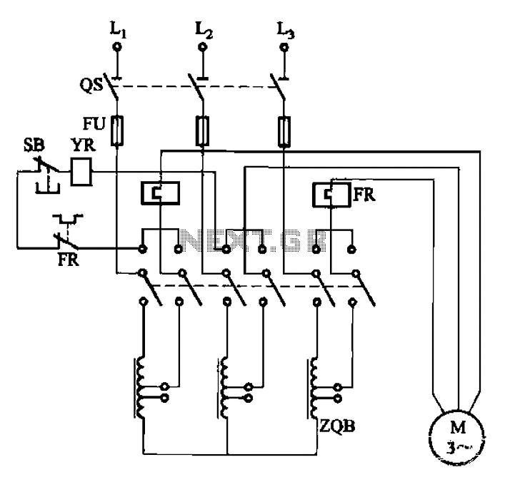
The circuit illustrated in Figure 3-47 involves a three-phase AC motor that is initially connected through a step-down autotransformer. To initiate operation, the power switch is closed, and the operating handle is pushed to the start position. Once the...