
Buffering TMP01 Temperature Sensor

The buffer circuit designed for the TMP01 temperature sensor serves to isolate the sensor's output from the load, ensuring that the sensor's performance is not affected by variations in load impedance. The TMP01 sensor provides an analog voltage output that is directly proportional to the ambient temperature, with a sensitivity of 5 mV per Kelvin. This means that for every degree Kelvin change in temperature, the output voltage changes by 5 mV.
In the schematic, the buffer circuit typically employs an operational amplifier (op-amp) configured as a voltage follower. The op-amp's non-inverting input is connected to the output of the TMP01 sensor, while the inverting input is connected to the op-amp output. This configuration allows the op-amp to provide high input impedance and low output impedance, enabling it to accurately follow the sensor's output voltage without loading it down.
Power supply connections for the op-amp must be considered, usually requiring dual supply voltages (e.g., ±15V or a single supply of 0V to 30V) depending on the op-amp specifications. Additionally, bypass capacitors should be placed near the power supply pins of the op-amp to filter out any high-frequency noise that may affect the performance of the circuit.
The output from the buffer can then be fed into an analog-to-digital converter (ADC) or other processing circuits, ensuring that the temperature readings are stable and accurate. Proper layout and grounding techniques should be applied to minimize noise and interference in the circuit, which is critical for maintaining the integrity of the temperature measurements provided by the TMP01 sensor.This is a buffer circuit for TMP01 Temperature Sensor. The output of this sensor is a low impedance dc output voltage with a 5 mV/K temperature coefficient.. 🔗 External reference
Related Circuits

This light sensor switch circuit enables the automatic activation of a lamp when ambient light levels decrease, such as during nightfall. The duration for which the lamp remains on can be adjusted using potentiometer P1, with a range of...

Sensing short circuits in equipment that operates underwater is particularly important. The wet-mat connector design shown in Figure 20-4 is also suitable for other remote short-circuit sensing applications. Due to the limitations imposed by the battery and voltage levels,...

Current sensing involves detecting the amount of current being used by a specific circuit or device. It is particularly useful for assessing the power consumption of various components within a robotic system. Although not commonly required in robotics, current...
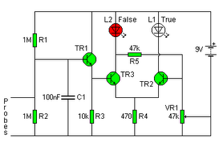
The following circuit illustrates a Lie Detector Circuit Diagram. Features include a capacitor that eliminates the 50Hz induced mains hum present in the circuit. The Lie Detector Circuit operates on the principle of measuring physiological responses, typically galvanic skin response...
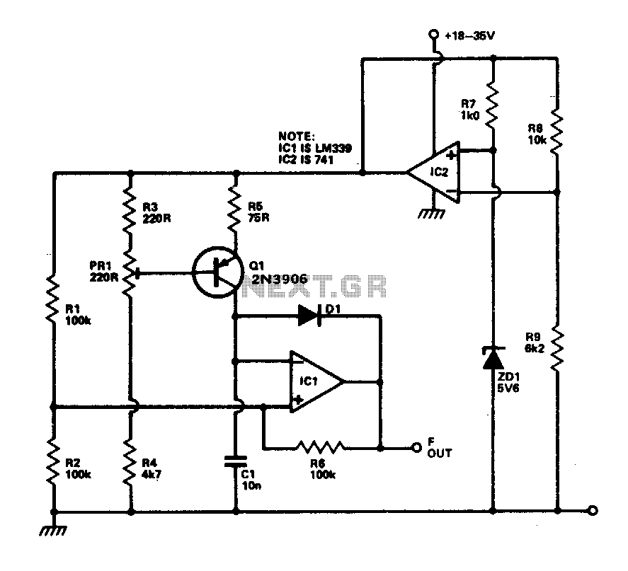
This circuit provides a linear frequency increase of 10 Hz per °C over a temperature range of 0 to 100 °C and can be utilized with logic systems, including microprocessors. The temperature probe Q1, utilizing the Vbe characteristic, changes...
A distance sensor would be a beneficial addition to Mindstorms robots; however, ultrasonic sensors tend to be bulky and power-intensive. Simple infrared methods, like those used in radar cars, can detect obstacles but do not provide accurate distance measurements....