
Light Detector

The circuit utilizes a light-dependent resistor (LDR) to detect variations in light intensity. The LDR's resistance decreases with increasing light levels and increases in low-light conditions. Resistor R2 plays a critical role in setting the voltage threshold for the operational amplifier (op-amp) 741. When the light intensity drops below a certain level, the increase in LDR resistance results in a decrease in voltage at the inverting input of the op-amp.
The 741 op-amp functions as a comparator in this configuration. The non-inverting input is supplied with a reference voltage through R2, which is calibrated to define the threshold light level. When the voltage at the inverting input falls below this reference voltage, the op-amp output transitions from a low state to a high state. This transition is indicative of a condition where the ambient light has fallen below the predefined threshold.
Upon the output of the op-amp going high, it activates transistor Q1. The transistor acts as a switch, allowing current to flow through the relay coil. The relay contacts, which are normally open, close upon activation. This closure can be used to control various devices or systems, such as lighting or alarms, based on the light intensity detected by the LDR.
In summary, the circuit effectively monitors light levels and utilizes a comparator to control a relay based on the light intensity. The design is suitable for applications requiring automatic control in response to ambient lighting conditions, showcasing the versatility of op-amps and transistors in electronic control systems. The circuit"s threshold is set by resistor R2. When the intensity of the light falling on the LDR is lowered, resistance of that unit increases, and lowers the voltage applied to the inverting input of the 741. The reference voltage at the noninverting input of the 741 is set (via R2) so that the comparator switches from low to high when the light falling on the LDR is reduced. That high activates transistor Ql, which causes the relay contacts to close.
Related Circuits
Nowadays, a switch-off delay for vehicle interior lighting is a standard feature. However, certain models with minimal settings or older vehicles leave users in the dark as soon as they enter and close the door. This situation calls for...
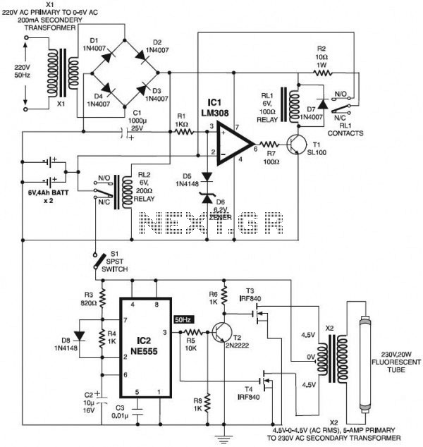
The circuit below is an automatic switch-on emergency light that utilizes an integrated circuit (IC) as an automatic controller, along with an overcharge protection feature. This circuit is designed to drive the system effectively. Additionally, there is a VU...
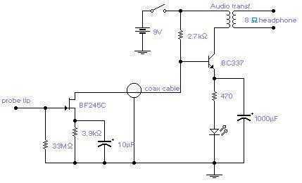
The circuit will come handy when you have to follow the mains wires buried in the wall or even water pipes provided they are not too far away (2-4cm max). It will also detect a conversation on a telephone...
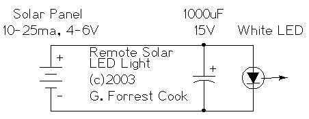
The remote solar powered LED light takes advantage of the current limited nature of solar photovoltaic cells. If light shines on the solar array, current will flow through the circuit. For a typical size of solar cell, there is...

The days of arriving home at night and entering into darkness are finally over. This is a highly practical device, and it has been designed as a module. This device is intended to provide illumination upon entering a dark space,...
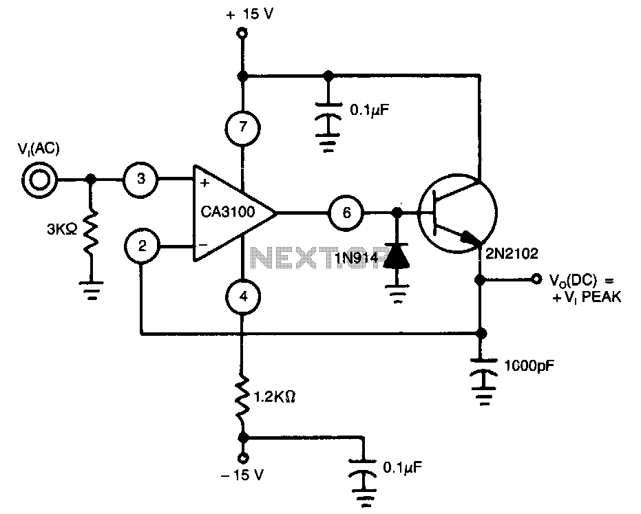
This peak detector utilizes a CA3100 BiMOS operational amplifier configured as a wide-band non-inverting amplifier, ensuring a nearly constant gain across a broad spectrum of input frequencies. The IN914 diode clips the negative half of the voltage defined by...