
Automatic Emergency Light

The automatic switch-on emergency light circuit is designed to activate during power outages or low-light conditions. The integrated circuit (IC) functions as the main controller, monitoring the power supply and automatically switching on the light when it detects a loss of power. The overcharge protection feature ensures that the battery charging process is regulated, preventing damage from excessive voltage or current. This is crucial for maintaining battery life and ensuring reliability during emergencies.
The VU meter circuit provides a visual representation of audio levels through the illumination of 12 LEDs. Each LED corresponds to a specific range of audio signal levels, allowing users to easily gauge the intensity of the input signal. The circuit can be calibrated to accommodate various input levels, making it versatile for different audio applications. This feature is particularly useful in audio mixing or sound engineering environments, where monitoring audio levels is essential.
The dancing LED circuit utilizes the NE555 timer, configured in astable mode to produce a continuous series of clock pulses. These pulses are fed into the CD4017 decade counter, which sequentially activates the LEDs in a dancing pattern. The NE555 timer's frequency can be adjusted by modifying the resistor and capacitor values in the circuit, allowing for customization of the LED dance speed. This circuit is not only visually appealing but also serves as an excellent demonstration of basic electronic components and their functionalities.
Together, these circuits showcase a range of applications from emergency lighting to audio level visualization and decorative lighting effects, making them valuable for both practical and educational purposes in electronics.The circuit below is an automatic switch-on emergency light. With IC as automatic controller, and and over charger protector. This circuit will drive the. Here is the VU meter with 12 LEDs circuit. This is an easy visual indicator of the audio level signals. Can be applied to various input levels, adjusted by. Here is a simple dancing LED circui t. Which based on NE555 & CD4017. NE555 is wired as an astable multivibrator to trigged the clock pulses for the CD4017. Pin. 🔗 External reference
Related Circuits
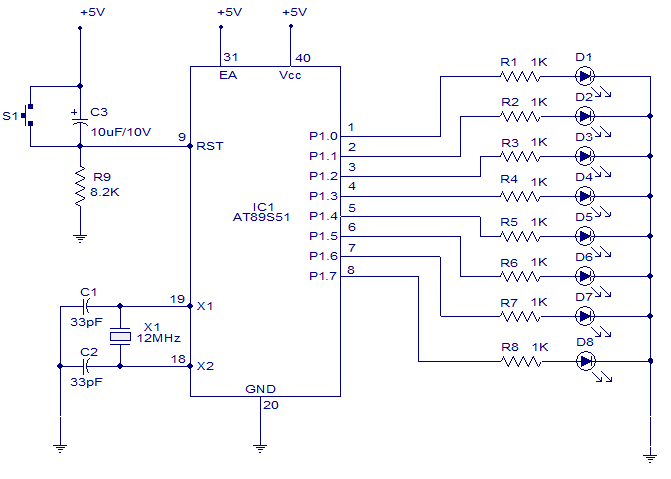
A six-function, eight-channel light chaser utilizing the 8051 microcontroller. The AT89S51, a member of the 8051 family, is employed to produce six distinct lighting sequences. The design incorporates straightforward software and hardware components. The circuit design features the AT89S51 microcontroller...
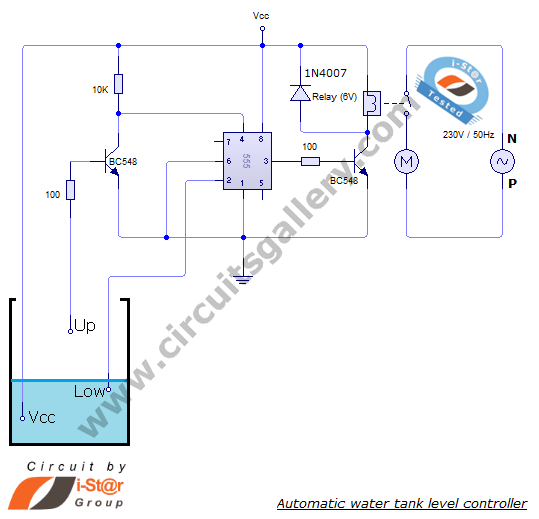
The automatic water level controller circuit is a straightforward engineering project that can automatically switch a domestic water pump on and off based on the water level in a tank. This motor driver circuit can be implemented at home...
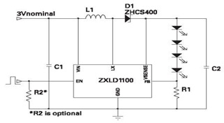
The ZXLD1100 is a PFM flyback DC to DC boost converter that operates in discontinuous mode. The following circuit diagram illustrates the configuration of four LED drivers for handset LCD backlighting using this device. The ZXLD1100 is designed to...

The circuit utilizes a 555 timer IC to create a lighting group delay effect, as illustrated in Figure 2-46. It consists of the 555 IC along with a resistor and capacitor configuration that establishes the delay. The circuit remains...
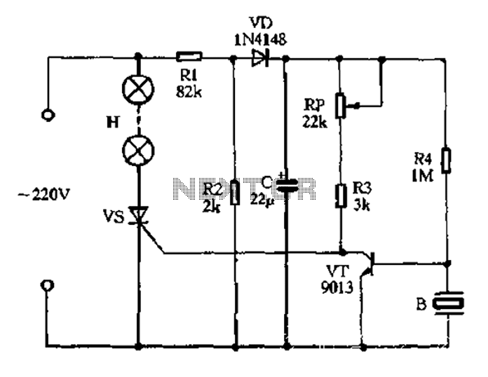
The circuit operates on 220V AC, utilizing resistors R1 and R2 to create a partial voltage drop. A VD half-wave rectifier converts this AC voltage to approximately 3V DC across capacitor C. An adjustment potentiometer RP is incorporated to...
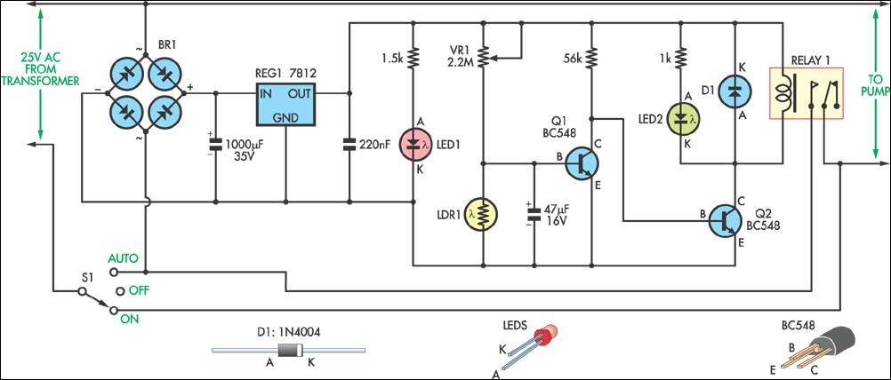
This circuit was designed to automatically control a garden pond pump, turning it on at dawn and off at dusk. This automation eliminates the need for manual operation, particularly beneficial during holidays when the owners are away. The controller...