
Simple Electric Field Detector

The described circuit functions as a non-invasive wire and signal detector, capable of sensing electrical fields from mains wires and telephone cables. The design primarily utilizes a transistor, where the gate lead acts as a sensitive probe. This probe is crucial for detecting electromagnetic fields emitted by live wires or cables in proximity, typically within a range of 2 to 4 centimeters.
The circuit's operation can be enhanced by using a plastic kitchen foil as a makeshift microphone, allowing it to pick up sound waves when placed appropriately. The 12mm gate lead of the transistor serves as the main sensing element, which is crucial for the circuit's performance. The inclusion of a 33M resistor, which should be soldered directly at the entry point of the gate lead into the transistor case, helps in stabilizing the circuit and ensuring accurate readings.
For signal transmission, a standard coaxial cable is employed, allowing for flexibility in the distance between the probe and the measuring or listening device. This setup can be particularly useful in situations where direct connection to the wires is impractical or unsafe.
To mitigate potential damage from high voltages, it is advisable to connect a pair of low leakage diodes (such as JPAD5) in a back-to-back configuration between the gate and ground. This addition provides a level of protection to the sensitive components within the circuit. However, caution is advised when handling the probe, as direct contact with electrified surfaces can lead to inaccurate readings or damage. A protective cover, such as a small piece of plastic sponge, is recommended to shield the probe tip from accidental contact with live circuits.
Overall, this circuit provides a versatile tool for detecting and analyzing electrical signals in a safe and effective manner, making it suitable for both professional and DIY applications.The circuit will come handy when you have to follow the mains wires buried in the wall or even water pipes provided they are not too far away (2-4cm max). It will also detect a conversation on a telephone cable without actually touching it (for testing purposes only) and it works as a microphone if you keep a plastic kitchen foil between the probe tip and your mouth.
The probe is just the 12mm long gate lead of the transistor. The 33M resistor should be cut short and soldered where the lead enters the transistor case. Connection to the other part of the circuit is via a standard coaxial cable of any length. The input is not protected and a pair of low leakage diodes (JPAD5) could be connected back to back between gate and ground. I did not find them necessary: I covered, with a small piece of plastic sponge, the probe tip to avoid direct contact with electrified surfaces and used a minimum of care when handling the probe.
🔗 External reference
Related Circuits

A, B, and C are used for a large power split-phase system. The A + BC range generator phase line features an A-A indole path string containing two 220V/15W bulbs. The bulbs recover based on macro instructions from J...
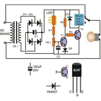
The left-hand side transistor T1 is configured as a voltage comparator utilizing a resistive network. The resistor in the upper arm is a light-dependent resistor (LDR), while the lower arm resistor is a preset resistor used to establish threshold...

This circuit diagram represents a highly sensitive electromagnetic field sensor capable of detecting electromagnetic fields in the frequency range of 40Hz to 140Hz. The low-noise operational amplifier LF351, along with its associated components, comprises the pick-up section. A 1µH...

This circuit is a motion detection sensor that utilizes a light source and detector as an infrared motion detector. It incorporates components such as a light-emitting diode (LED), a phototransistor, a transmitter, a receiver, an NE555 timer configured as...

Capacitive touch sensors operate based on the electrical capacitance associated with the human body. When a finger approaches the sensor, it establishes a capacitance to the ground, typically ranging from 30 to 100 pF. This phenomenon can be utilized...

This circuit diagram represents a simple electronic combination lock utilizing the IC LS7220. The circuit is designed to activate a relay for controlling any device (on and off) each time a specific combination of four digits is entered. It...