
LIGHT DIMMER

The 555 timer operates in astable mode, generating a continuous square wave output that can be used to control the brightness of a light source. In this configuration, the duty cycle of the output signal can be adjusted by varying the resistance values of Ra and Rb, which are effectively represented by the 47K potentiometer. The capacitor connected to the timing circuit sets the frequency of oscillation, which is approximately 300 Hz in this application.
The circuit includes a power MOSFET, specifically the TO-220 package type such as the MTP3055E, which is capable of handling higher current loads necessary for driving incandescent bulbs or other resistive loads. The MOSFET acts as a switch that regulates the power delivered to the light source based on the PWM signal generated by the 555 timer.
A heat sink is essential for the MOSFET to prevent overheating during operation, especially at full rated loads. The design ensures that the MOSFET operates within safe temperature limits, enhancing reliability and performance.
In summary, this light dimmer circuit effectively utilizes the 555 timer's astable configuration to create a variable duty cycle output, allowing for precise control of light intensity through the adjustment of the potentiometer. The inclusion of a suitable heat sink for the MOSFET is critical for maintaining optimal performance and preventing thermal failure.The 555 timer "light dimmer" schematic circuit is shown in figure 1 below. For the light dimmer to work the 555 timer is configured as a "variable cycle", astable oscillator running some where around 300 Hz. The power mosfet used here would be a TO-220 type such as MTP3055E or similar. Note the need for a TO-220 type heat sink for full rated loads. If you look back at the tutorial on 555 timers (figure 2a - modified duty cycle in astable operation) you will note the need for Ra and Rb. Cunningly this is provided for in our light dimmer circuit by using a 47K potentiometer (often marked 50K).
In 🔗 External reference
Related Circuits
Dark Activated Switch or Porch Light Switch. This circuit activates a relay when the light level drops below a preset threshold. The light sensitivity can be adjusted using variable resistor VR1, and the relay contacts can control an external...
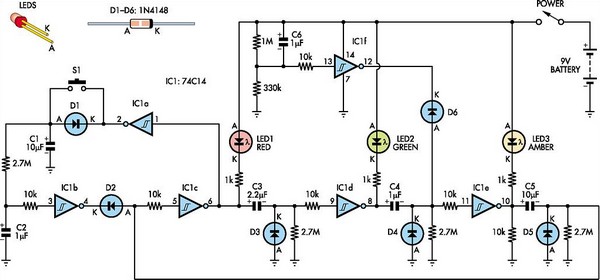
This toy traffic signal utilizes a single low-cost hex Schmitt-trigger inverter IC (IC1a-IC1f) to directly control three colored LEDs (red, green, and amber). Upon activation, the circuit illuminates the red signal for 30 seconds, followed by green for 6...
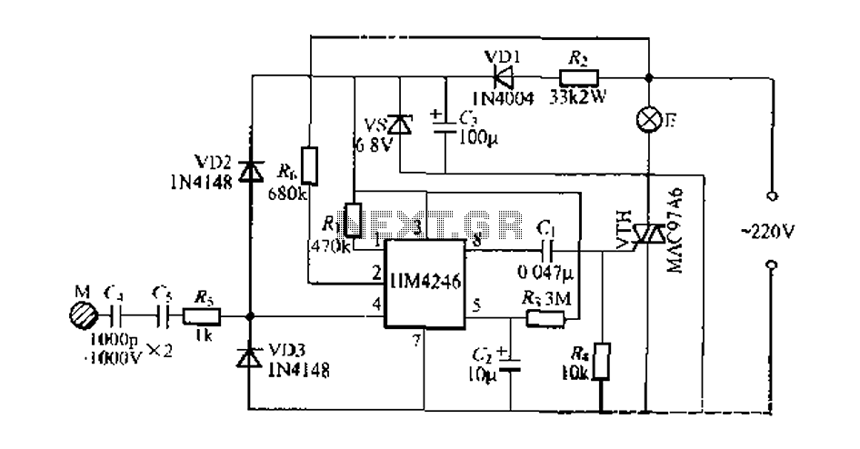
Development and production of a specialized touch dimmer integrated circuit. This circuit features four lighting functions: dark, medium, light, and a touch-sensitive trigger on all four sides. It has low harmonic radiation emission, high touch sensitivity, and stability. It...
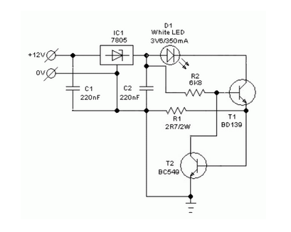
A simple and safe white LED driver circuit has been designed for use in 12V automobiles, allowing for the efficient operation of standard high-efficiency white LED modules powered by automotive battery systems. The circuit utilizes a fixed voltage regulator...
This circuit utilizes a 555 timer to control a 4017 decade counter. The outputs from the counter are used to drive transistor relay drivers. The duration for which the lights remain "on" can be adjusted by modifying the connections...
These relatively simple circuits can be used to transmit information across a small distance. The information typically used includes music from a radio, iPod, or CD player; a microphone and amplifier can also be utilized. People frequently transmit information...