
TRAFFIC LIGHT SEQUENCER CIRCUIT

The circuit begins with the 555 timer configured in astable mode, generating a continuous square wave output. This output serves as the clock signal for the 4017 decade counter, which counts the number of pulses received. The 4017 has ten outputs, each corresponding to a count from 0 to 9, which can be utilized to control different devices or lights.
Each output of the 4017 is connected to a transistor relay driver. These drivers are essential for switching higher power loads, such as lamps or motors, that cannot be directly controlled by the logic-level outputs of the 4017. The transistors act as switches, allowing the low-power output from the 4017 to control the high-power devices.
To adjust the time that the lights remain "on," the connections of the outputs from the 4017 can be altered. For instance, by connecting multiple outputs to a single relay driver, the duration of the "on" state can be extended, as the relay will remain activated until all connected outputs have cycled through. This flexibility allows for a variety of timing configurations depending on the desired application.
Overall, this circuit is suitable for applications where sequential lighting or timed activation of devices is required, such as in decorative lighting displays, automated signage, or alarm systems.This circuit uses a 555 timer to drive a 4017 counter. The counter outputs drive transistor relay drivers. Time lights "on" can be proportioned by changing connections of outputs of counter. 🔗 External reference
Related Circuits
Craftsman Garage Door Opener Schematic and Installation Manuals. Sears Craftsman Garage Door Opener Parts. With 15 years in the business, Garage Door Openers Superstore is a leading provider. The schematic for the Craftsman Garage Door Opener provides a comprehensive overview...
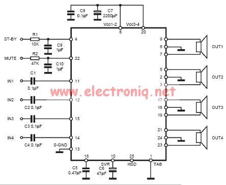
The input capacitor is used for low-frequency cut-off, with a standard value of 0.1 µF, resulting in a cut-off frequency of approximately 16 Hz. The input capacitor plays a crucial role in filtering unwanted low-frequency signals in electronic circuits. By...
The transmitter's function is to modulate the original signal frequency of the message-carrying signal, a process known as modulation. The circuit realization of this function is referred to as a frequency modulation (FM) circuit. FM tuners are categorized into...
Below are three examples of controlling a relay from the PC's parallel printer port (LPT1 or LPT2). Figure A shows a solid-state relay controlled by one of the parallel port data lines (D0-D7) using a 300-ohm resistor and a...
This circuit is a soft light dimmer that utilizes the IGBT STGP10N50A and the TS555 timer as its primary components. The soft light dimmer circuit is designed to control the brightness of incandescent lamps or other resistive loads by...
This circuit can be used to operate an electric strike or an electromagnetic lock on a door. It is not the door being opened/closed, but a small electromagnetic strike which unlocks the door. The opener has the following features...