
Interactive Toy Traffic Lights

The circuit employs a hex Schmitt-trigger inverter IC, which is advantageous for its ability to provide clean and stable switching transitions, minimizing the risk of false triggering that can occur with noisy signals. The use of colored LEDs not only serves a functional purpose in signaling but also enhances the visual appeal of the toy. The timing intervals are carefully selected to simulate realistic traffic light behavior, making this circuit an effective educational tool for teaching basic electronics and timing circuits. The inclusion of protective resistors and diodes ensures the longevity and reliability of the components, making this toy traffic signal a robust design for both educational and recreational applications. Overall, this circuit exemplifies a practical application of digital logic and timing principles in a straightforward and engaging manner.This toy traffic signal uses a single low-cost hex Schmitt-trigger inverter IC (IC1a-IC1f) to directly drive three coloured LEDs (red, green and amber). At switch-on, the circuit lights the red signal for 30s, then shows green for 6s, then amber for 3s. It then repeats the sequence. Interaction is provided by pushbutton S1 which abbreviates the re d period to a further 3s only, if it is pressed while the red signal is showing. Sequencing of the three LEDs is controlled by inverters IC1c, IC1d & IC1e, while the electrolytic capacitors at the inverter outputs and their associated 2. 7MO resistors determine how long each LED stays on. Diodes D3, D4 & D5 discharge the timing capacitors for the next two LEDs in the sequence while the current LED is on.
Note also the 10kO resistor at the input of each inverter. These protect the inverter inputs from being damaged by the negative voltage produced when the previous output goes low while its timing capacitor is fully charged. The circuit is forced into the red state at switch-on by IC1f and its associated circuitry. What happens is that IC1f briefly pulls the negative end of the amber timing capacitor (C4) low via D6 at switch-on.
As a result, IC1e`s output goes high and turns the amber LED (LED3) off. The red timing capacitor (C5) is in a discharged state at power-up because D5 and the 10kO resistor at the output of IC1e discharge it when the power is off. As a result, when IC1e`s output goes high, IC1c`s output goes low and turns LED1 (red) on. This also pulls the input of IC1d low, so IC1d`s output goes high, turning the green LED off. The amber timing capacitor (C4) at the output of IC1d charges rapidly when it receives the negative pulse from IC1f.
That`s because its positive end is high when the green LED is off and the pulse takes its negative end low. When pin 12 of IC1f subsequently goes high at the end of the switch-on pulse, this remains charged and holds the input of IC1e low, so the amber LED (LED3) remains off.
Pushbutton operation is controlled by IC1a and IC1b, which rapidly charge the red timing capacitor (C5) 3s after switch S1 is pressed. This works as follows: pin 2 of IC1a is high when the red LED is on, so pressing S1 during the red period rapidly charges C1.
C2 then charges slowly from C1 via a 2. 7MO resistor. After about 3s, C2 reaches IC1b`s trigger threshold and so pin 4 of IC1b switches low. Because the red LED is on, the amber LED is off. This means that pin 10 of IC1e is high and so the positive end of C5 is also high. When IC1b`s output goes low, it pulls the negative end of C5 low via D2, thereby rapidly charging this timing capacitor. This ends the red period and so the red LED (LED1) turns off. As a result, IC1a`s output goes low and C1 and C2 discharge via D1, ready for the next time switch S1 is pressed.
🔗 External reference
Related Circuits
The 15V DC supply is derived from a nominal 230/24V center-tapped AC transformer (T1) and a full-wave rectifier (D5 & D6). A Zener diode (D4) is included to limit the DC voltage to a maximum of 15V. Triacs (D7,...
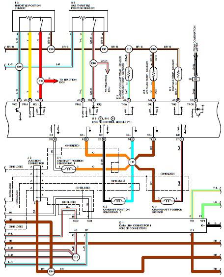
1995 Toyota Supra Electrical Circuit Diagram. Features: shown from the point where the power source is received from the battery as far as each component. The 1995 Toyota Supra electrical circuit diagram provides a comprehensive overview of the vehicle's electrical...
This circuit is intended to drive the various lights decorating the crib prepared during Christmas season at many homes in Latin Countries, especially for children delight, in order to obtain realistic light-effects. The circuit design for driving lights in a...
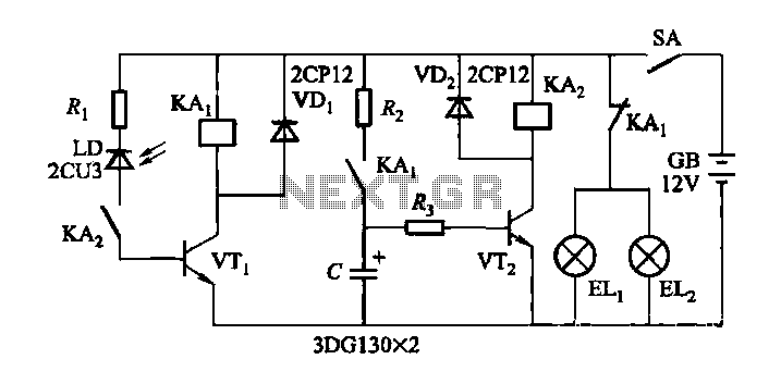
When driving at night and approaching another vehicle, traffic regulations dictate that the distance between the two vehicles should be maintained. This is achieved by alternately activating and deactivating the high beams, while utilizing either the wide lights or...
The terminal of R7, indicated by an arrow, must be connected to the desired output pin of IC2 or IC3 to select the number of LEDs or clusters that will form the bar. For instance, to drive seven LEDs...
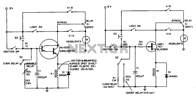
This circuit maintains the headlights of an automobile in an on state temporarily. It also ensures that the lights turn off automatically, even if the user forgets to switch them off manually. The shut-off delay is activated only when...