
Trigger Circuit Controls Stop-Motion Camera System

The system required a trigge r mechanism to set the timing in motion. The input trigger needed by the system controller is a pulse train of at least two pulses. After the system is armed, the first incoming pulse acts as a pre-trigger, and the second is the final trigger for the system. The circuit can use either an optical trigger (a light curtain ) or a sonic trigger. With very minor modifications, it can work with both triggers. The parts are all through-hole components, chosen for availability. The trigger circuit comprises five major components: the sensor, the conditioner, the pulse generator, the opto-isolator, and the power conditioner ( Fig.
1 ). The power conditioner, which is not discussed in this article, supplies both positive and negative 9 V to all the circuitry on the board, using an LM317 and an LM337, respectively. For several reasons, the trigger circuit uses an opto-isolated output. First, due to the sensitivities of the controller, I had to ensure that no ground loops were present.
Previous tinkering had shown that they could cause random firing of the system controller. Second, the voltage levels ( ±9 V) used on this board aren`t compatible with the system controller circuitry (+5 V). Finally, the flash circuit (on another board) could potentially cause a large ground bounce (a 10- µs discharge of about 1200 V) that could damage circuitry elsewhere.
Note that the opto-isolator base connection (pin 6) is left floating. The trigger input is an electret microphone. The microphone has a four-terminal connector, two resistive +9-V pins, and two returns, but only two of these pins are used. You can substitute an LED and photodiode pair for the electrets. If so, one of the devices uses one pair of power/return pins, and the other device uses the other pair.
In both cases, the sensor hot is tied to the resistive power output that comes back through the 22- µF capacitor. The capacitor blocks dc, allowing only the pulse from the photodiode or noise from the electret through to the signal-conditioning circuit.
The signal-conditioner circuit employs an OP-400, just because I had several on hand ( Fig. 2 ). Any modern quad op-amp could be used. R12 is used primarily as a load/impedance matching device for the sensor. U2a is configured to deliver a variable voltage gain of from zero to about 20. U2b and U2c provide a gain of approximately 100 for U2a`s output. Once the circuit is built, you can adjust R7 to get the appropriate output at U2d. Obviously, differing amounts of gain were required for the optical and electret circuits. R16, D1, and C3 form a pulse-shaping network that ensures that the output of U2d is a pulse or series of pulses. Finally, U2d provides a small amount of gain to the pulse and reverses its polarity to match the next stage of the system.
This negative-going pulse is sent through C5 ( Fig. 1, again ) to the pulse-generation circuit. C5 blocks the dc voltage VPos (+9 V) from the output of U2d. R14 is a pull-up resistor that ensures the input to the pulse-generation circuit is correct. When all is working correctly, the input to the pulse-generation circuit is an active-low trigger. R17 was left unpopulated. It was originally unknown if it would be needed in real hardware, so the ability to install it was left in the printed-circuit board (PCB). The pulse-generation circuit is simply two 555 timer devices, one fed into the other ( Fig. 3 ). The first (U5) is set up as a one shot. That is, an input trigger causes a single positive pulse to come out of pin 3. The length of this pulse can be adjusted by changing R27 🔗 External reference
Related Circuits
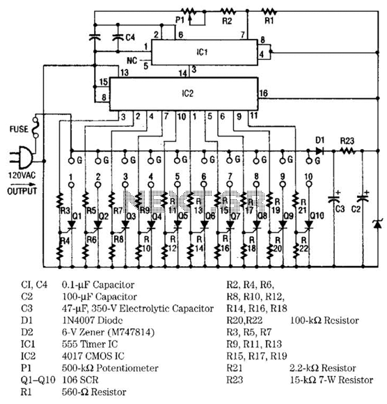
The light sequencer employs two integrated circuits (ICs) and ten silicon-controlled rectifiers (SCRs) to create an alternating current (AC) sequencer. The first IC, a 555 timer, is configured as an astable multivibrator to generate clock pulses for the second...
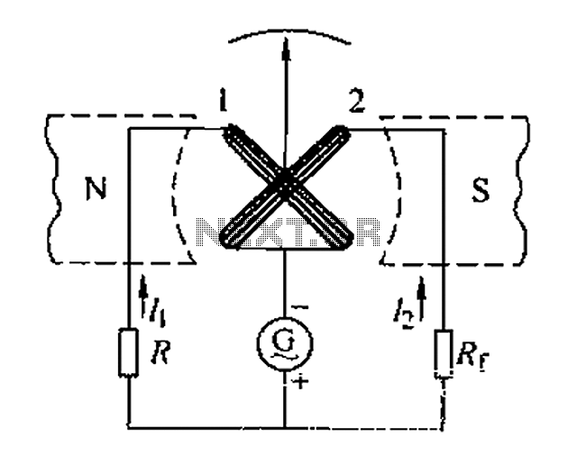
Also known as a megger insulation resistance meter, this device measures resistance at the megohm level. It is primarily used to assess the insulation resistance of motors, electrical circuits, and equipment. Additionally, it helps determine whether there is circuit...
The single-junction transistor is commonly utilized in sawtooth and pulse generators, and it can also be configured to create a basic sine wave generation circuit. As an oscillator circuit composed of discrete components, it requires a minimal number of...
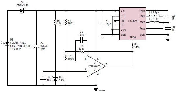
A simple supercapacitor charger electronic project can be designed using the LTC3625 integrated circuit (IC) from Linear Technology. This circuit is capable of charging two supercapacitors in series to a fixed output voltage of either 4.8V/5.3V or 4V/4.5V, which...
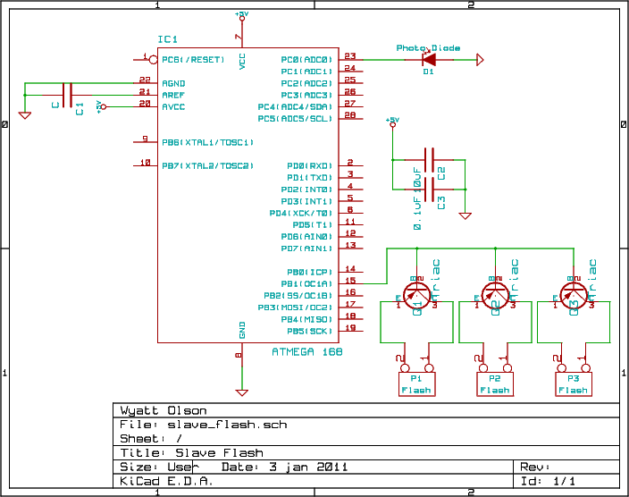
This project involves a slave flash capable of triggering up to four camera flashes in non-TTL mode. It is designed for use with the Nikon CLS system but may also function with other brands that share similar protocol heuristics....
Ensure to verify all connections utilizing the circuit diagram and breadboard schematic available for download from the provided links. This resource can assist during the assembly process. To create a reliable electronic circuit, it is essential to meticulously verify all...