
Light Fence Security Beeper

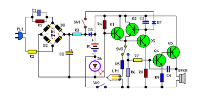
This light fence security beeper circuit is designed to detect interruptions in a light beam, triggering an alarm when the beam is broken. The main components of the circuit include a 12 Volt DC power supply, a photo transistor (T1), a green LED (D1), and an audible alarm or beeper.
In the idle state, the green LED (D1) emits light, which is directed towards the photo transistor (T1). The photo transistor is designed to conduct when it receives light, allowing current to flow through the circuit and keeping the alarm in a non-triggered state. The circuit is configured such that when an object or person interrupts the light beam, the light reaching T1 is reduced, causing the photo transistor to stop conducting. This change in state can be detected by the circuit, which activates the alarm.
The circuit can be adjusted for sensitivity by modifying the resistor values in the circuit. For instance, changing the resistor connected to the photo transistor can increase or decrease the amount of ambient light required to trigger the alarm. Additionally, the circuit can be enhanced by adding a delay timer to prevent false alarms caused by small animals or moving objects that briefly interrupt the light beam.
For installation, the LED should be positioned to project light across the area to be monitored, while the photo transistor should be placed at the opposite end to receive the light. This configuration creates a light barrier that, when breached, activates the alarm mechanism.
Overall, this simple light fence security beeper circuit provides an effective and low-cost solution for various security applications, ensuring that any unauthorized access is promptly detected and signaled.General purpose hobby circuit of a simple light fence security beeper is presented here. This circuit can be used as a door alarm, gate alarm, pathway alarm, etc. Any 12 Volt dc power supply can power the whole circuit.Working of this circuit is straight forward. In standby mode photo transistor T1 receives light from the green LED (D1) and T1 conducts to di.. 🔗 External reference
Related Circuits

VD1, VD2, C1, and C2 comprise a simple half-wave rectifier capacitor step-down voltage regulator circuit, providing an output of approximately 12V for a linear power supply connected to the LM386. The LM386 is linked to the inverting input terminal...

It utilizes the mains supply through a basic DC rectifier circuit. The circuit operates by converting alternating current (AC) from the mains supply into direct current (DC) using a rectifier. A typical implementation involves a bridge rectifier configuration, which consists...

The circuit is designed to seek light, enabling it to follow a flashlight in a darkened environment. Two photocells are utilized to determine the direction of movement for the robot. Each photocell connects to an operational amplifier (op-amp) configured...
This circuit is permanently connected to a mains socket for the trickle charging of Ni-Cd batteries. In the event of a power outage, the lamp automatically turns on. Alternatively, an alarm sounder can be selected instead of the lamp....
This is same circuit as above with the addition of a photo resistor to trigger the flip flop instead of a push button. The bias resistor in series with photo resistor was chosen so that sufficient voltage is present...

22W by Ct and R, RC Buck, rectified by n. c, filtering. vz 3V DC regulated output power, before U, V2 and MIC power supply. When the audio signal reaches the beam, the microphone MI converts acoustic energy into...