
light flasher pcb

This LED flashing circuit utilizes the 555 timer IC in an astable mode, which is a common application for generating square wave signals. The frequency of the output signal, which determines the flashing rate of the LEDs, is influenced by the resistor values and the timing capacitor used in the circuit. The formula for calculating the frequency (f) of the output signal in an astable configuration is given by:
f = 1.44 / ((R1 + 2R2) * C)
Where R1 and R2 are the resistances connected to the 555 timer, and C is the capacitance of the timing capacitor. By adjusting these components, the user can control the flashing rate of the LEDs.
To implement the circuit, the following components are required:
- 1 x NE555 timer IC
- 1 x capacitor (10μF or higher for adjustable flashing rates)
- 2 x resistors (R1 and R2, values to be determined based on the desired frequency)
- 1 x 330-ohm resistor for the alternating LED configuration
- 2 x LEDs (for alternating flashing)
- Power supply (typically 5V to 15V depending on the LEDs and timer specifications)
The circuit can be built on a breadboard or a PCB for more permanent applications. The layout should ensure that the connections are secure, and the power supply is correctly polarized to prevent damage to the components.
In the alternating flasher configuration, when the LEDs are connected at points X and Y, the circuit will alternate the flashing of the two LEDs, enhancing the visual effect. The capability of the 555 timer to handle up to 200mA allows for a significant number of LEDs to be connected in parallel, making this circuit suitable for decorative lighting applications, indicators, or visual signals in various electronic projects.
Overall, this circuit serves as an excellent introduction to timer-based applications and provides a practical demonstration of how to control LED behavior using simple electronic components.This is a very basic circuit for flashing one or more LEDS and also to alternately flash one or more LEDs. It uses a 555 timer setup as an astable multivibrator with a variable frequency. With the preset at its max. the flashing rate of the LED is about 1/2 a second. It can be increased by increasing the value of the capacitor from 10uF to a highe r value. For example if it is increased to 22uF the flashing rate becomes 1 second. There is also provision to convert it into an alternating flasher. You just have to connect a LED and a 330ohm as shown in Fig. 2 to the points X and Y of Fig. 1. Then both the LEDs flash alternately. Since the 555 can supply or sink in upto 200mA of current, you can connect upto about 18 LEDS in parallel both for the flasher and alternating flasher (that makes a total of 36 LEDs for alternating flasher). 🔗 External reference
Related Circuits

This page features a circuit that has twenty open collector outputs that turn on one at a time in a continuous sequential manner. The circuit utilizes the 74LSxx family of TTL integrated logic devices. The circuits are designed to...
The schematic diagram below illustrates a typical 1.5V flasher circuit using the LM3909. The LM3909 is a monolithic oscillator designed specifically for flashing Light Emitting Diodes (LEDs). The LM3909 flasher circuit operates at a low voltage of 1.5V, making it...

The circuit utilizes a VDI-VD4 bridge rectifier to convert 220V AC into a full-wave pulsating voltage, which powers lights H1 to H4. A buck regulator, composed of resistor R3 and diode VD4, reduces this voltage to approximately 5V DC,...
This is same circuit as above with the addition of a photo resistor to trigger the flip flop instead of a push button. The bias resistor in series with photo resistor was chosen so that sufficient voltage is present...
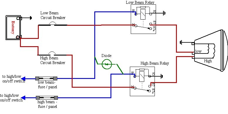
There is a need for improved headlights. Research has been conducted, including participation in ongoing forum discussions; however, basic information is still required. To enhance the performance of vehicle headlights, several factors must be considered, including the type of bulbs...

An LED flasher circuit can be constructed using a 555 integrated circuit (IC). The use of the 555 IC allows for greater flexibility in adjusting the flashing rate of the LED. This LED flasher circuit is similar to other...