
Light flashing circuit

The light flashing circuit typically consists of a few key components: a power source, a lamp (LED or incandescent), a resistor (R1), and a timing element, which can be a capacitor and a transistor or an integrated circuit (IC) designed for timing applications.
In this configuration, the resistor R1 is crucial for controlling the current flowing to the lamp. By adjusting R1, the voltage across the lamp can be varied, effectively changing the brightness and the flashing rate. The timing element, often implemented with a capacitor (C) and a transistor, establishes the timing cycle. The capacitor charges and discharges through R1, creating a time delay that results in the one-second flashing interval.
For a basic implementation, a common timing circuit can be based on a 555 timer IC configured in astable mode. In this setup, the 555 timer generates a square wave output, which can be used to drive the lamp. The frequency of the oscillation is determined by the values of R1, R2 (another resistor), and C.
The standard formula for calculating the frequency (f) of the output signal in an astable 555 timer circuit is given by:
f = 1.44 / ((R1 + 2 * R2) * C)
By selecting appropriate values for R1, R2, and C, the desired flashing rate can be achieved. Adjustments to R1 allow for fine-tuning of the flash rate while maintaining the overall functionality of the circuit.
Safety considerations should be taken into account, especially when working with higher voltages or currents. Proper heat dissipation methods for the lamp and the components should be ensured to prevent overheating and potential damage.
This light flashing circuit can be applied in various applications, such as decorative lighting, signaling devices, or as an attention-grabbing indicator in electronic projects.Light flashing circuit.
Related Circuits
To achieve optimal audio reproduction at varying listening levels, it is essential to adjust tone control settings to align with the established characteristics of human auditory perception. The sensitivity of the human ear changes non-linearly across the entire audible...
Introduction The SP6648 integrated synchronous boost regulator is a compact circuit that provides ultra-high efficiency drive current for an LED flashlight using a Luxeon I light source. The circuit is configured to deliver a constant output current of 350mA...
This high voltage converter circuit begins with a 30-volt power supply and is capable of delivering output voltages ranging from 0 to 3 kV for version 1, or from 0 to 10 kV for version 2. The high voltage converter...
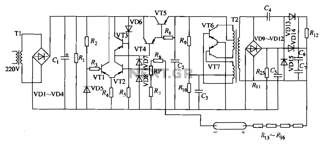
The DC power supply is a helium-neon laser excitation power supply, which is currently the most commonly used type of power supply. It is utilized in laser printers. The circuit includes a power transformer (T1), a high-voltage transformer (T2),...
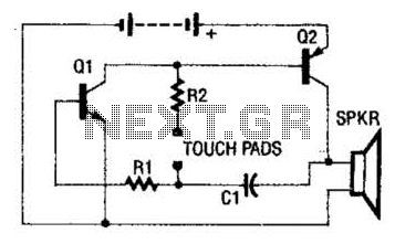
The circuit employs a two-transistor direct-coupled oscillator, with its frequency determined by capacitor C1, resistor R2, and the skin resistance across the touch pads. Since C1 and R2 are fixed values, only the skin resistance can vary the sound...
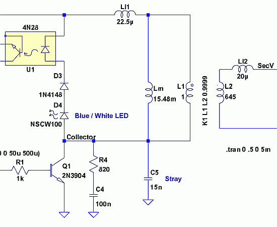
Since then, NL has evolved into the Microsoft Windows®-based NL4, which has been extensively used by world-class engineers in various fields of electronics for almost 10 years. NL5 is the first version to be publicly available. Unlike conventional SPICE-based...