
Bright light control circuit diagram of a precision
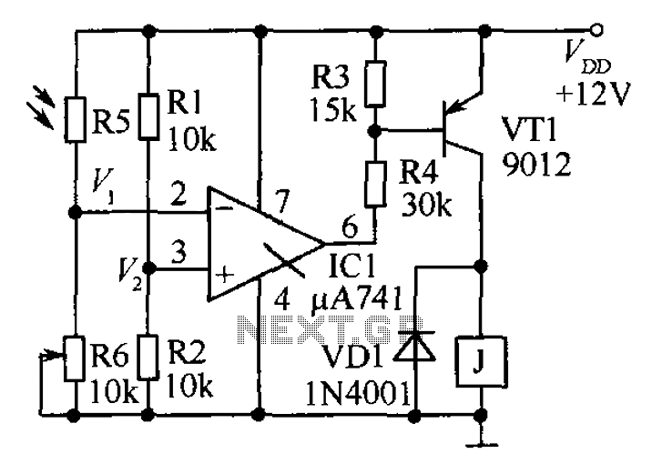
The precision bright light control circuit utilizes a Wheatstone bridge configuration to achieve stable performance regardless of variations in power supply voltage and environmental conditions. The primary components include resistors R1, R2, R6, and the photosensitive resistor R5.
In this configuration, the two-arm Wheatstone bridge is designed to measure the resistance changes in the photosensitive resistor R5, which varies with light intensity. When light levels increase, the resistance of R5 decreases, causing an imbalance in the bridge circuit. This imbalance generates a voltage difference that can be used to control an output device, such as a light dimmer or an automatic lighting system.
Resistors R1 and R2 are typically fixed values that help set the reference voltage levels for the bridge, while R6 can be adjusted to calibrate the sensitivity of the light detection. The circuit is designed to maintain a consistent output signal, ensuring that fluctuations in supply voltage or temperature do not affect the performance of the light control mechanism.
This circuit is particularly useful in applications where precise light control is necessary, such as in photography, horticulture, or automated lighting systems, where maintaining consistent light levels is critical for optimal performance. As shown in the circuit as a precision bright light control circuit, its work is not affected by the power supply voltage and ambient temperature. Resistors R1, R2, R6 and phot osensitive resistance R5 together constitute two-arm Wheatstone bridge.
Related Circuits
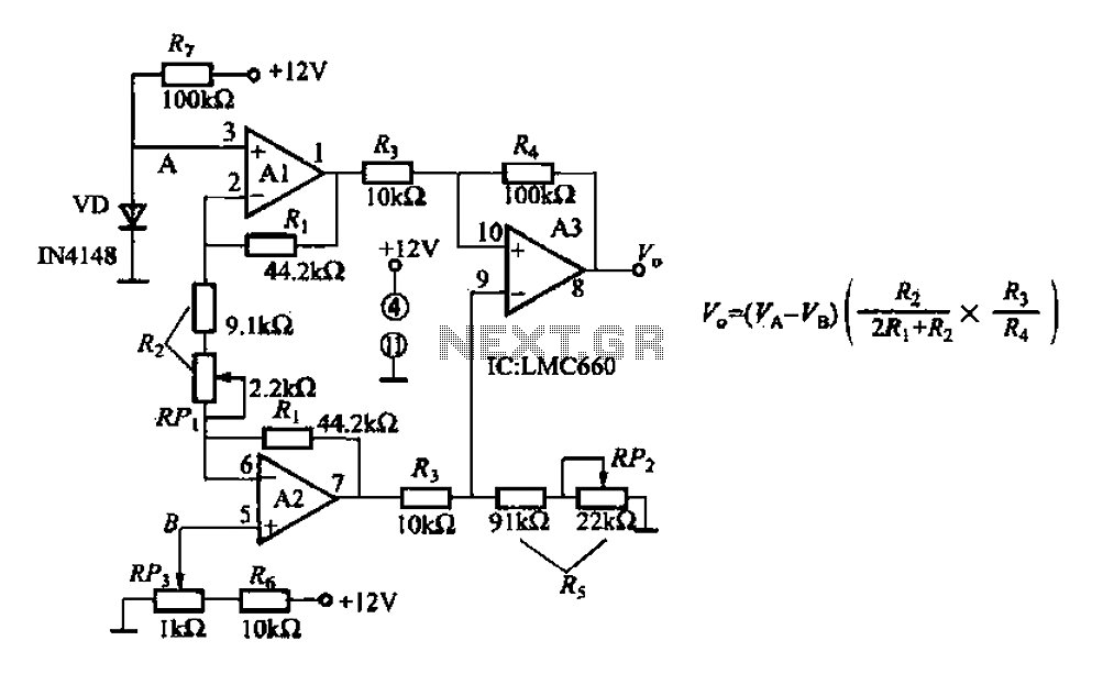
A diode IN4148 temperature circuit is presented. The circuit operates within a temperature range of -25 to 125 degrees Celsius, with an accuracy of 0.5. The core components of the operational amplifier circuit consist of four LMC660 amplifiers. It...
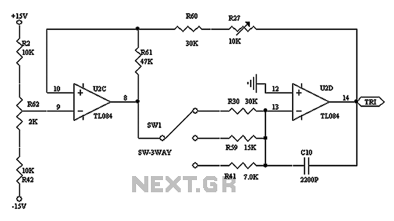
The triangular wave circuit consists of two operational amplifiers (OPs). R62 serves as the offset adjustment, while R27 is utilized for peak adjustment. A switch is included to select different resistances, allowing for the generation of triangular waves at...
For example, I do not understand the process of demodulation or the modulation itself, and so on. Is there someone who can understand this circuit? Could you please assist me? The circuit in question likely involves a modulation and demodulation...
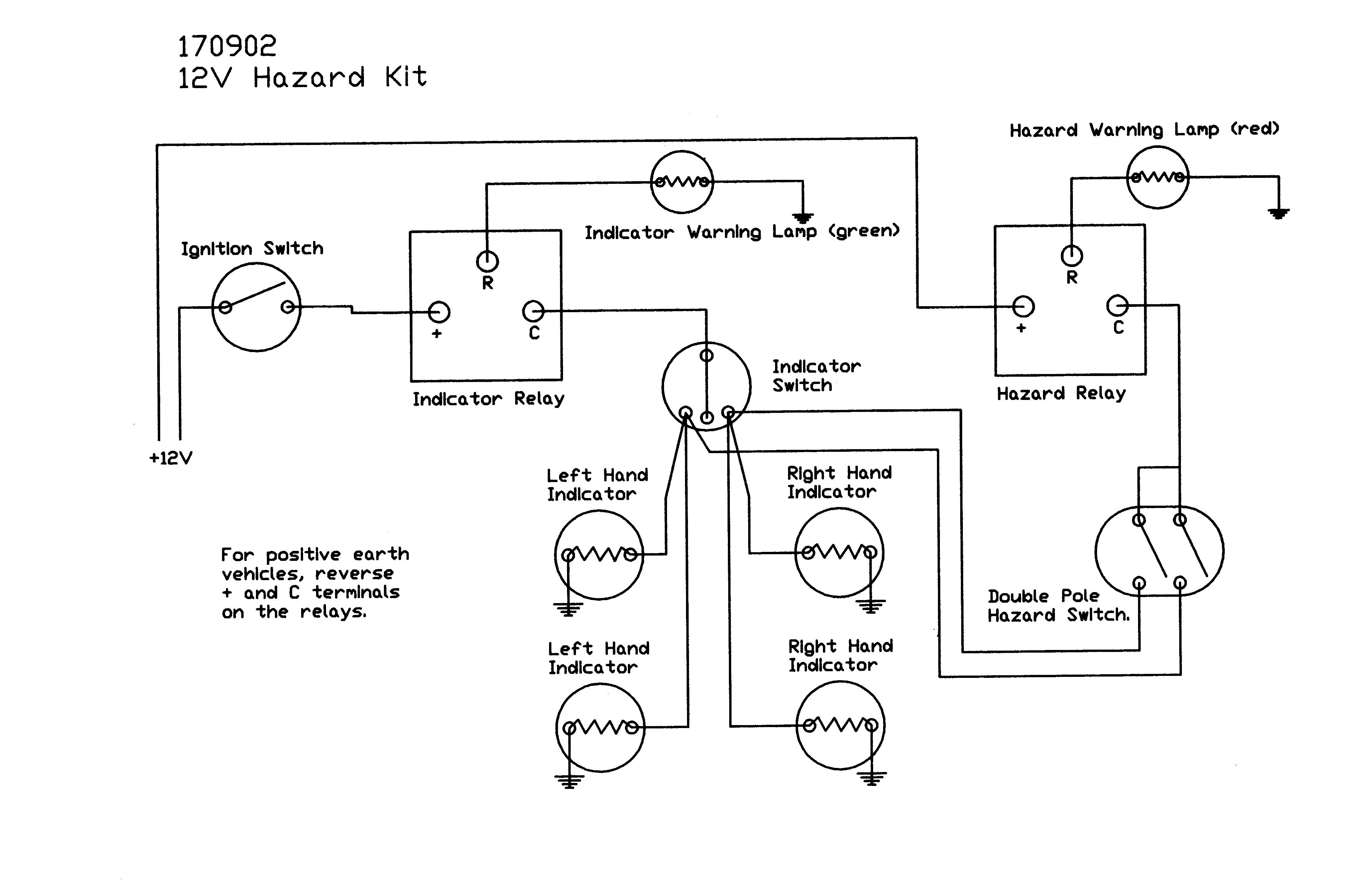
This diagram provides a basic understanding of the system's operation. The only point where the left and right indicators converge from the indicator switch is between the stalk and the hazard switch. It is advisable to remove the steering...
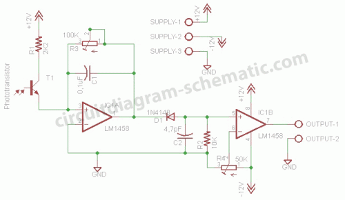
This circuit is a motion detection sensor that utilizes a light source and detector as an infrared motion detector. The motion sensor employs an infrared LED and a phototransistor. Since it relies on light, the sensor's sensitivity can be...
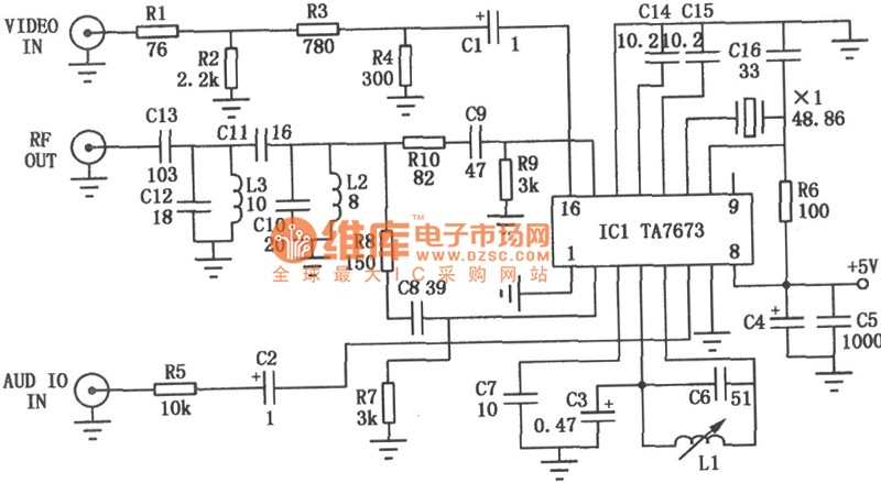
The RF modulator is a crucial component in televisions, VCRs, satellite receivers, format converters, home computers, and gaming consoles. This circuit is straightforward, stable, and easy to construct, allowing for seamless integration with various circuit boards. The schematic diagram...