
RF Modulator Circuit Composed of TA7673

The RF modulator circuit is designed to convert baseband video signals into radio frequency (RF) signals suitable for transmission over coaxial cables. The TA7673 integrated circuit serves as the core of the modulator, facilitating the modulation process through its internal architecture. The circuit typically includes components such as resistors, capacitors, and inductors that work together to filter and amplify the signal, ensuring high-quality output.
In operation, the modulator receives composite video input, which is then processed to create an RF output. The modulation technique employed can vary, but it often involves amplitude modulation (AM) or frequency modulation (FM) to encode the video signal onto a carrier frequency, typically within the VHF or UHF bands. The output can be connected directly to a television or other RF-compatible devices.
The design also incorporates power supply considerations, ensuring that the modulator operates efficiently and reliably. Proper grounding and shielding techniques are essential to minimize interference and maintain signal integrity. The circuit can be adapted for various applications by modifying the output frequency or adjusting component values to meet specific requirements.
Overall, the RF modulator circuit is an essential building block in modern electronic systems, enabling the seamless transmission of audio-visual content across different platforms and devices.The RF modulator is the very important component in TV, VCR, satellite receiver, format converter, home computer and game machine. This circuit is simple, stable and easy to make, it can be easily connected with a lot kinds of circuit boards.
The figure is the circuit of RF modulator, ICl is the modulator ASIC (TA7673), the 10-pin and 11-pin generate the ima.. 🔗 External reference
Related Circuits
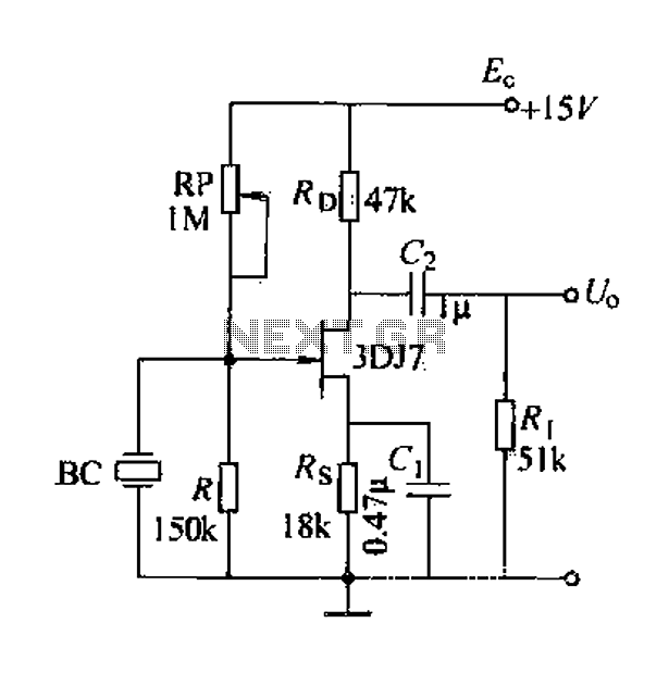
A field effect transistor (FET) voice amplifier has a low input impedance, approximately 1 kΩ, requiring the signal source to provide a constant current signal for operation. Unlike bipolar transistors, FETs are voltage-controlled devices that draw minimal current at...
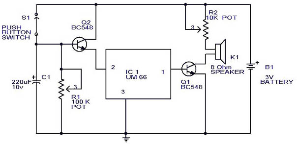
This circuit is a slight modification of a previous design. In the earlier version, the switch needed to be held down for the entire duration of the music playback. In this updated circuit, pressing the push button once charges...
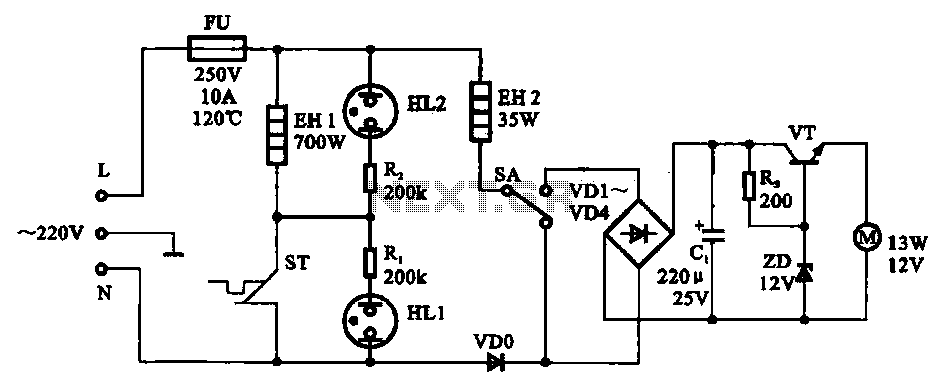
The electric thermos temperature detection control circuit is designed to monitor and manage the temperature within an electric thermos. It primarily consists of a control circuit for the boiler heater and heater insulation, an electrical magnetic pump motor drive...
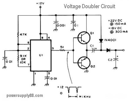
This circuit diagram represents a DC voltage doubler and DC converter. It is designed to convert a 12V DC power supply into outputs of 24V DC and 18V DC. Nearly any PNP or NPN power transistors can be utilized...
The LED blinks as expected, then pauses for an indefinite duration, flashes again a different number of times, and turns off again, displaying no discernible cyclic behavior. It activates without any external input, indicating that there is likely no...
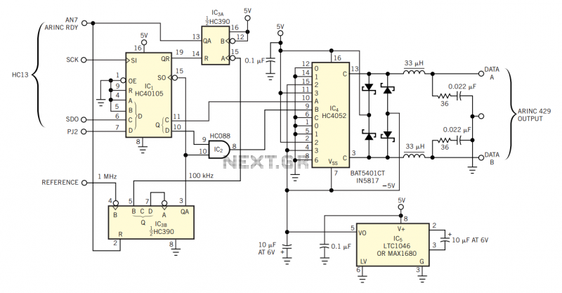
The physical transmission medium for the 429 standard is 78Ω shielded, twisted-pair cable that uses a complementary, differential bipolar RZ (return-to-zero) waveform. The voltages are the net differentials that the biphase drive develops: For example, the differential is 10V...