
Led Flasher with a BC547 NPN transistor
The described flasher circuit utilizes a single driver transistor to control the flashing of a high-brightness white LED. The circuit operates by leveraging the charging and discharging characteristics of a 100µF electrolytic capacitor, which is crucial to the timing of the LED's illumination. The flash rate is inherently linked to the characteristics of the LED being used; specifically, a standard LED is unsuitable for this application, necessitating the use of a high-brightness variant.
In the configuration, a 1kΩ resistor is placed in parallel with the electrolytic capacitor to facilitate its discharge. This resistor plays a critical role in determining the brightness and flash rate of the LED. By adjusting this resistor to higher values, such as 4.7kΩ or 10kΩ, the discharge rate of the capacitor is altered, which in turn affects the flash intensity of the LED. When a higher resistance (like 10kΩ) is employed, the capacitor does not fully discharge, resulting in a dimmer flash from the LED due to insufficient current flow during the charging phase.
The transistor in the circuit acts as a switch, turning on when the capacitor begins to charge. The charging current flows through the LED, causing it to light up. The arrangement of components is critical; each part must be positioned according to the circuit diagram for optimal functionality. This circuit design is effective for applications requiring a simple flashing LED indicator, providing a clear visual signal while allowing for some degree of control over brightness through resistor selection.This is a novel flasher circuit using a single driver transistor that takes its flash-rate from a flashing LED. The flasher in the photo is 3mm. An ordinary LED will not work. The flash rate cannot be altered by the brightness of the high-bright white LED can be adjusted by altering the 1k resistor across the 100u electrolytic to 4k7 or 10k.
The 1k resistor discharges the 100u so that when the transistor turns on, the charging current into the 100u illuminates the white LED. If a 10k discharge resistor is used, the 100u is not fully discharged and the LED does not flash as bright. All the parts in the photo are in the same places as in the circuit diagram to make it easy to see how the parts are connected.
🔗 External reference
Related Circuits

This circuit is designed as a warning flasher to alert road users to dangerous situations in low-light conditions. It can also function as a bicycle light, subject to applicable traffic regulations. White LEDs are recommended for use as a...
In the circuit below, 60 individual LEDs are used to indicate the minutes of a clock and 12 LEDs indicate hours. The power supply and time base circuitry is the same as described in the 28 LED clock circuit...
The circuit involves infrared phototransistor pairs positioned at three locations within a maze, including the endpoint. The maze is designed to be narrow enough for a single finger to slide through, and as fingers pass the phototransistors, a sound...
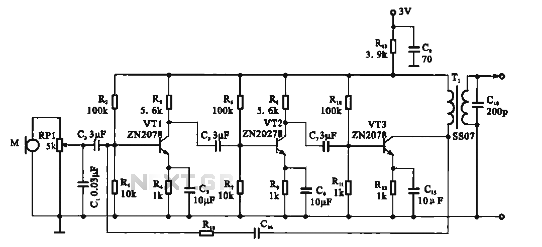
This circuit is a recording signal amplifying transistor circuit that illustrates the functioning of a microphone signal amplifier. After adjustment through potentiometer RP1, the signal is applied to the transistor VT1, which operates as a common emitter amplifier. The...
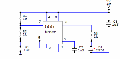
This circuit is built around one of the most popular timer integrated circuits, the 555 timer. It will flash the LED on and off at regular intervals. From left to right, the two resistors and the capacitor set the...
This simple and inexpensive circuit is not limited to Christmas use. It consists of two resistors, a small-signal transistor such as a BC547, and a flashing LED. The circuit operates by utilizing a small-signal transistor, which acts as a switch...