
Recording signal amplifying transistor circuit

The recording signal amplifying circuit is designed to effectively capture and enhance audio signals from a microphone. The use of a common emitter configuration for transistor VT1 allows for significant amplification of the input audio signal. The adjustment via potentiometer RP1 provides flexibility in tuning the gain to accommodate various microphone sensitivities and recording conditions.
The negative feedback resistor connected to the emitter of VT1 plays a crucial role in stabilizing the DC operating point, ensuring consistent performance across different operating temperatures and signal conditions. Capacitor C3 acts as a decoupling element, which is essential for filtering out noise and preventing oscillations that could degrade the quality of the amplified signal.
Transformer T is pivotal in this circuit, as it not only couples the amplified audio signal to the recording head but also serves to match impedance between the amplifier and the recording device. The secondary winding of the transformer, in conjunction with the 200 pF capacitor, is specifically designed to boost high-frequency response, addressing the common issue of high-frequency signal loss during the recording process.
The feedback network involving capacitor C16 and transistor TV1 is instrumental in refining the frequency response of the amplifier. This feedback mechanism allows for better control over the amplifier's gain across a range of frequencies, ensuring that the output remains clear and defined even at higher frequencies.
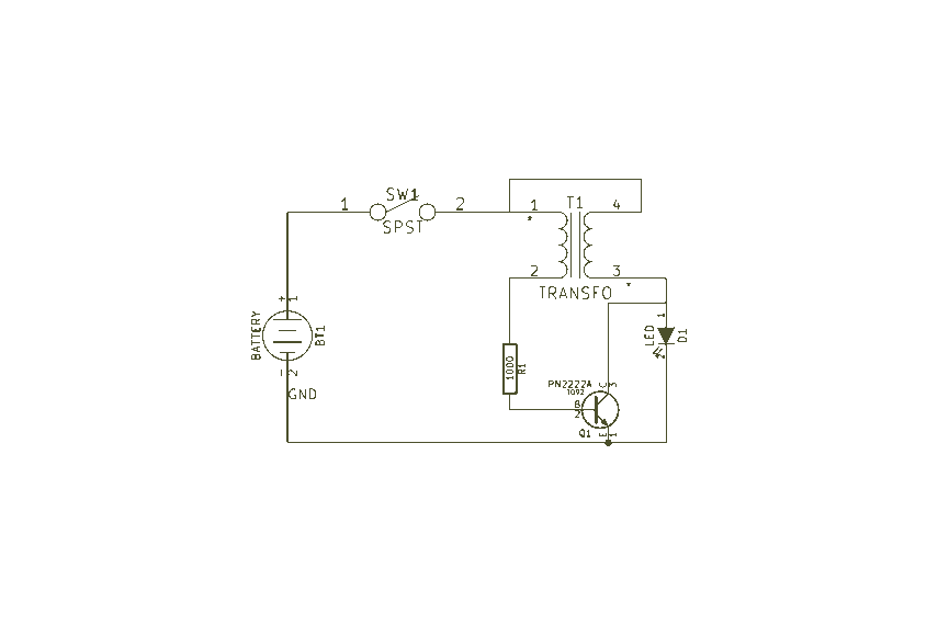
The circuit's design also emphasizes low power consumption, making it suitable for battery-operated devices. The use of a 3V power supply derived from two batteries allows for extended operation without frequent replacements, which is particularly advantageous in portable recording applications. This combination of features makes the recording signal amplifying transistor circuit a robust solution for high-quality audio recording tasks.Recording signal amplifying transistor circuit Shows the recording signal transistor amplifier, the microphone signal after adjustment by potentiometer RP1 applied to the transistor VT1, it is a common emitter amplifier, where VT1 emitter connected to the current negative feedback resistor as a stable DC operating point, C3 to decoupling capacitor so that VT1 exchange gain increase, the audio signal after amplification levels applied to the transformer T, the primary winding. By transformer coupled audio signal to the recording head for recording. Transformer secondary winding and 200 pF capacitor in parallel to enhance the high-frequency signal, the recording process to compensate high-frequency losses.
VT3 collector outputs Rcs. C16 TV1 feedback to the base, with spout improve the frequency characteristics of the amplifier. The output of the amplifier with variable pressure mode can compensate for high frequency signals. 3V low voltage power supply circuit by the use of two batteries, and has a low power consumption characteristics.
Related Circuits
Easy Joule Thief Soldering Kit from MakersBox on Tindie The Easy Joule Thief Soldering Kit is designed for educational purposes, allowing users to learn about basic electronics through hands-on experience. This kit includes all necessary components to assemble a Joule...
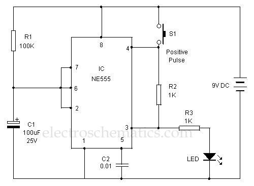
This 555 timer is designed uniquely to provide a positive output through control over its reset pin. Typically, the 555 timer IC is triggered by applying a negative voltage. The 555 timer is a versatile integrated circuit widely used in...
It is well known that pests like rats, mice, etc., are repelled by ultrasonic frequency in the range of 30 kHz to 50 kHz. Human beings can't hear these high-frequency sounds. Unfortunately, all pests do not react at the...
Sur ce site, il est possible de trouver des contributions dans des domaines d'intérêt variés. Il est également possible de suivre l'auteur sur Twitter : @davbucci. Le site est constitué de contributions hétérogènes. L'accès se fait via les liens...
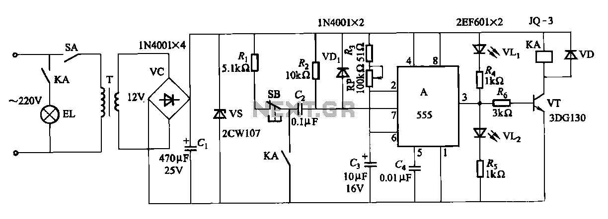
The second circuit for darkroom time exposure utilizes a 555 timer integrated circuit (IC A) for timing functions. A relay controlled by the circuit regulates the exposure light source. The exposure time can be adjusted using potentiometer RP, allowing...
China's national conditions indicate that the general living room area exceeds twenty square meters, often serving as a bedroom or listening room. For speakers with a sensitivity of 89 dB or higher, a pure Class A amplifier with a...