
LED Running message Board CD4017

The described circuit utilizes light-emitting diodes (LEDs) arranged to form letters, which illuminate sequentially to display a message. The central component of this circuit is the CD4017 decade counter (IC2), which is responsible for the sequential activation of the outputs corresponding to the letters. The CD4017 has ten decoded outputs, allowing it to control multiple LEDs efficiently.
The timing for the LED sequencing is provided by the NE555 timer (IC1), configured as an astable multivibrator generating a clock pulse at a frequency of 1 Hz. This clock pulse is fed into the CD4017, which advances its output on each pulse. The first output activates on reset, illuminating the first letter 'W' through transistor T7. The subsequent clock pulses shift the activation to the next letters in the sequence, with transistor T6 illuminating the letter 'E' on the first pulse after 'W'.
The circuit ensures that previously lit letters remain illuminated due to the forward biasing of the transistors through diodes, allowing for a continuous display until the entire message is shown. After the complete sequence, the circuit resets, and the process begins anew. The sequencing speed can be adjusted using a variable resistor (potmeter VR1), allowing for customization of the display speed.
The LED array can be mounted on a veroboard, with a common ground connection to a power supply ranging from 6V to 9V. The anodes of the LEDs connect to the emitters of the respective transistors, ensuring controlled illumination. The versatility of this circuit allows for the integration of numerous LEDs, enabling the creation of custom designs, such as LED fashion jewelry. Additionally, by connecting multiple circuits in a multiplexed configuration, a more dynamic moving display effect can be achieved.Light emitting diodes are advan- tageous due to their smaller size, low current consumption and catchy colours they emit. Here is a running message display circuit wherein the letters formed by LED arrangement light up progressively.
Once all the letters of the message have been lit up, the circuit gets reset. The circuit is built around Johnson decade counter CD4017BC (IC2). One of the IC CD4017BEs features is its provision of ten fully decoded outputs, making the IC ideal for use in a whole range of sequencing operations. In the circuit only one of the outputs remains high and the other outputs switch to high state successively on the arrival of each clock pulse.
The timer NE555 (IC1) is wired as a 1Hz astable multivibrator which clocks the IC2 for sequencing operations. On reset, output pin 3 goes high and drives transistor T7 to ?on? state. The output of transistor T7 is connected to letter ?W? of the LED word array (all LEDs of letter array are connected in parallel) and thus letter ?W? is illuminated. On arrival of first clock pulse, pin 3 goes low and pin 2 goes high. Transistor T6 conducts and letter ?E? lights up. The preceding letter ?W? also remains lighted because of forward biasing of transistor T7 via diode D21. In a similar fashion, on the arrival of each successive pulse, the other letters of the display are also illuminated and finally the complete word becomes visible. On the following clock pulse, pin 6 goes to logic 1 and resets the circuit, and the sequence repeats itself.
The frequency of sequencing operations is controlled with the help of potmeter VR1. The display can be fixed on a veroboard of suitable size and connected to ground of a common supply (of 6V to 9V) while the anodes of LEDs are to be connected to emitters of transistors T1 through T7 as shown in the circuit. The above circuit is very versatile and can be wired with a large number of LEDs to make an LED fashion jewellery of any design.
With two circuits connected in a similar fashion, multiplexing of LEDs can be done to give a moving display effect. 🔗 External reference
Related Circuits
This circuit, designed on request, has proven to be useful to indicate when the voltage in a power supply line is changing from 120V to 240Vac. It can be used in different circumstances and circuits, mainly when an increase...
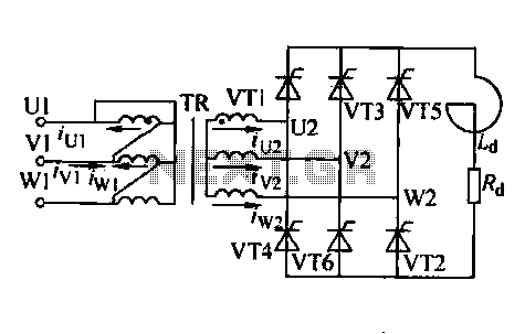
Trigger circuit routing forms include various types such as simple trigger circuits, single-junction transistor trigger circuits, synchronous sine wave trigger circuits, sawtooth transition phase shift (synchronous) trigger circuits, and integrated trigger circuits. This section presents individual cases for introduction...
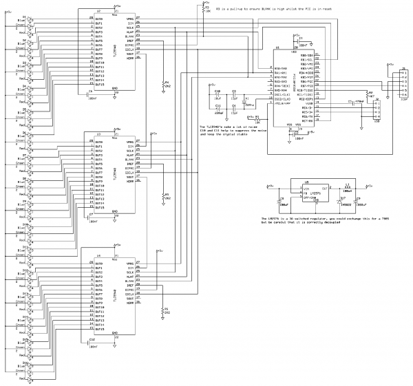
This project creates an RGB LED VU Meter controlled via USB by a host machine running Windows 7 or Vista. It serves multiple purposes: it demonstrates the ability to read audio information from the Windows machine and transmit it...

An RS flip-flop, also known as a reset-set flip-flop, is a type of stable multivibrator that has two inputs: reset and set. The output can exist in one of two stable states. The RS flip-flop is a fundamental building block...
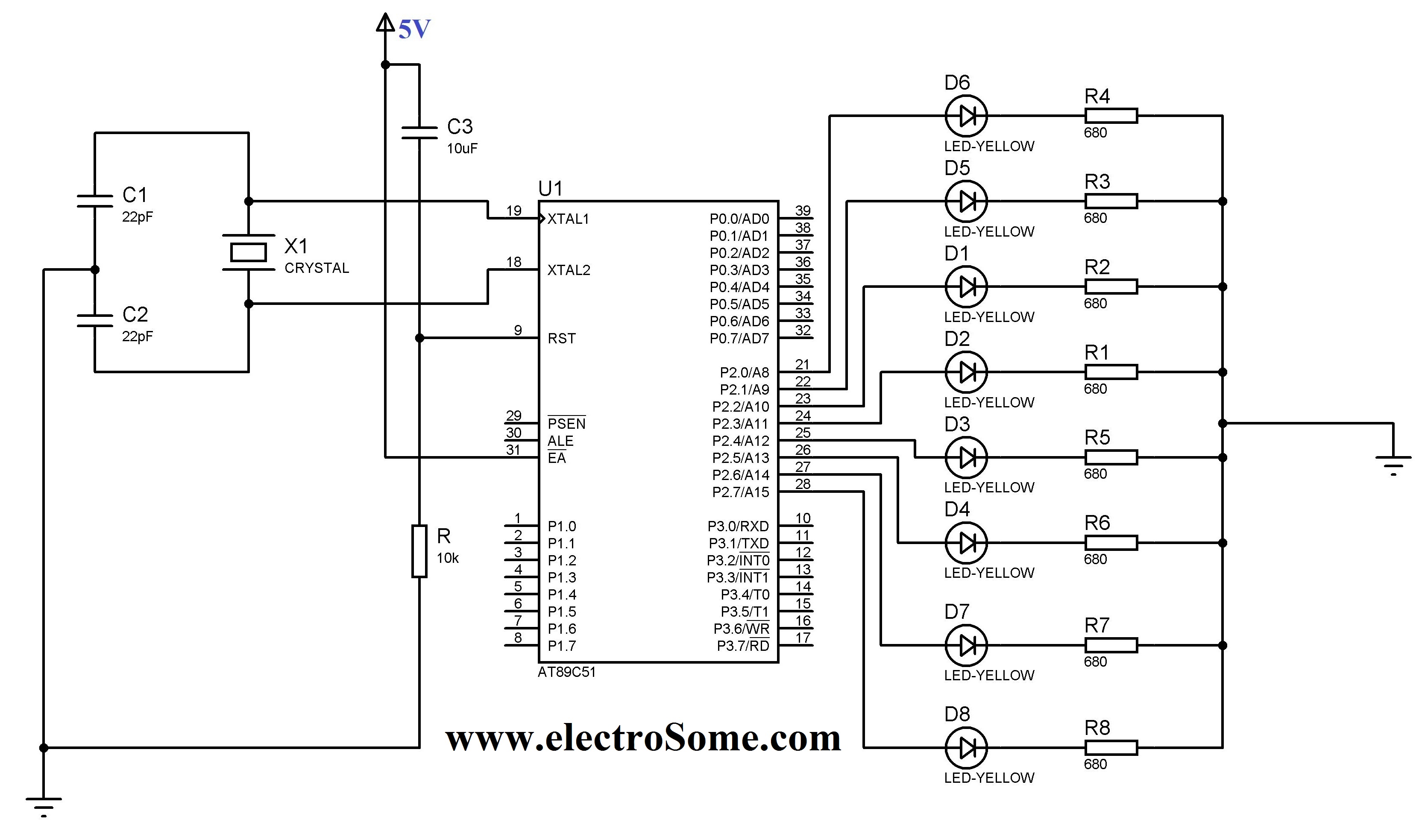
The 8051 controller is mask-programmable, meaning it is programmed during manufacturing and cannot be reprogrammed afterward. However, the AT89C51 microcontroller, a derivative of the 8051, is reprogrammable. This device includes a timer, a serial port interface, and interrupt control,...
A very popular type of LED that has finally emerged is the tri-color, RGB LED. The RGB stands for red, green, and blue, as the LED is capable of displaying various colors through the combination of these three primary...