
Opto-Coupled RS Flip-Flop

The RS flip-flop is a fundamental building block in digital electronics, frequently used for data storage and synchronization in sequential circuits. It operates by taking two binary inputs, labeled as R (reset) and S (set). The flip-flop transitions between its two stable states based on the conditions of these inputs.
When the S input is activated (set to high), the output Q transitions to a high state, while the output Q' (the complement of Q) transitions to a low state. Conversely, when the R input is activated, the output Q transitions to a low state, and Q' transitions to a high state. If both inputs are low, the flip-flop maintains its previous state, exhibiting the memory characteristic of the device.
It is essential to avoid activating both inputs simultaneously, as this condition leads to an undefined state, which can cause unpredictable behavior in the circuit. The RS flip-flop can be implemented using various components, including NAND or NOR gates, depending on the desired logic configuration.
In practical applications, the RS flip-flop is used in memory storage, frequency dividers, and as a basic building block for more complex memory elements such as D flip-flops and JK flip-flops. Understanding the operation and characteristics of the RS flip-flop is crucial for designing reliable digital systems and circuits.RS flip-flop, or reset-set flip flop, is a kind of stable multivibrator with two input, namely reset and set. The output will be at one of two stable states,.. 🔗 External reference
Related Circuits
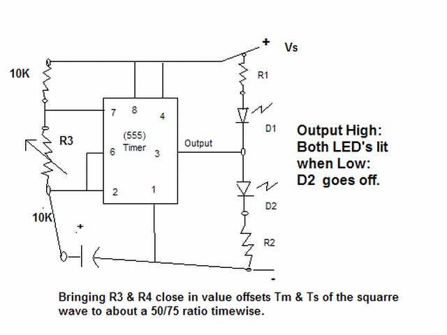
The output signal is configured to go high for approximately 0.5 seconds and then low for around 1.33 seconds. However, there is an issue present. The circuit in question likely employs a timing mechanism to achieve the specified output signal...
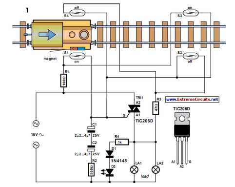
Modern electronics is essential for every large model railroad system, providing solutions to nearly every issue. Although ready-made products are available... Modern model railroad systems rely heavily on advanced electronics to enhance functionality and user experience. These systems often incorporate...
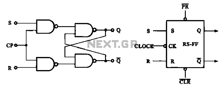
The asynchronous RS flip-flop mentioned earlier is not synchronized with the system clock signal. In contrast, the synchronous RS flip-flop incorporates synchronization, allowing it to operate in conjunction with the clock signal. Figure (a) illustrates the circuit configuration of...
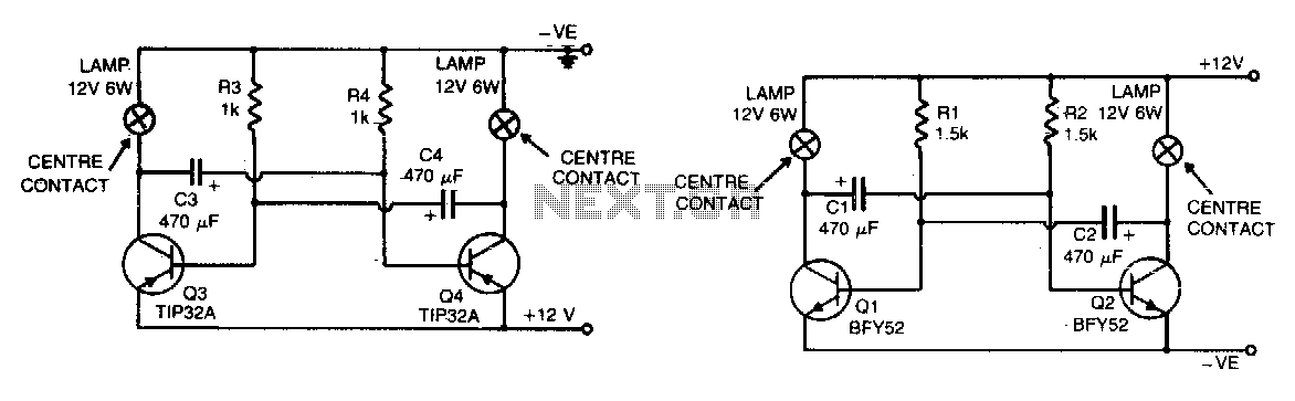
The flashing action is generated by a basic astable multivibrator configured to produce a flashing rate of approximately 60 flashes per minute for each lamp. The circuit designed for positive earth systems employs NPN transistors, while alternative configurations utilize...
The CLOCK input indicates that it is edge-triggered, responding to abrupt changes in voltage rather than gradual changes or steady logic levels. The CLOCK input of the 4013 D-type bistable is specifically rising-edge triggered, meaning it only reacts to...

This is a pulse stretcher circuit utilizing an optocoupler. The circuit employs a 4N26 optocoupler in conjunction with a standard one-shot circuitry. The pulse stretcher circuit is designed to elongate the duration of an incoming pulse signal, which is particularly...