
Light Level Droplets Detector

The Low-Light Level Drop Detector circuit is designed to sense minute variations in ambient light conditions, making it suitable for applications in environments where light levels are consistently low. The self-biasing configuration employed in this circuit allows it to maintain a stable operating point without the need for external biasing components, enhancing its sensitivity to light changes.
The core of the circuit typically consists of a photodetector, such as a photodiode or phototransistor, which converts light into an electrical signal. This signal is then processed through an operational amplifier configured in a transimpedance mode, allowing for the conversion of the current generated by the photodetector into a voltage signal. The gain of the operational amplifier can be adjusted to optimize the circuit's sensitivity to light variations.
In addition, the circuit may include a filtering stage to eliminate noise and enhance the signal-to-noise ratio, ensuring that only significant changes in light levels are detected. The output can be further processed or used to trigger other devices, such as alarms or lighting systems, based on the detected light levels.
Overall, the Low-Light Level Drop Detector circuit is an effective solution for monitoring and responding to subtle changes in lighting conditions, making it valuable in various applications, including automatic lighting control, security systems, and environmental monitoring.This is a circuit of Low-Light Level Drop Detector. This circuit utilize self-biasing configuration to detect small changes in light level. This circuit.. 🔗 External reference
Related Circuits
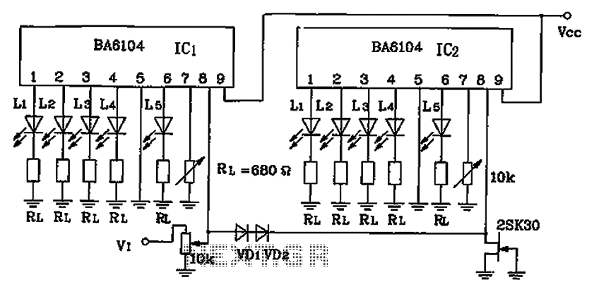
BA6104 is a five-digit LED level meter that functions as an LED display driver integrated circuit (IC). The configuration of the circuit is illustrated in the accompanying figure. The circuit utilizes a 10 by two-dot LED level display. The...
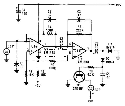
A piezoelectric detector (BZ1) is utilized in this circuit to sense variations in air pressure. BZ1 generates a voltage that is amplified by U1A and U1B. The frequency response is restricted to low frequencies. The signal is rectified by...
Dynamic flip-flops ignore pulses at their inputs that are shorter than 40 ns or do not have TTL levels. This limitation renders TTL flip-flops inadequate for capturing noise pulses with unknown durations and amplitudes. This issue is familiar to...
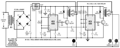
This is a simple traffic light controller that can be used to teach children the basics of traffic light rules. The circuit employs commonly available electronic components and consists of rectifier diodes (1N4001), a 5V regulator (7805), two timer...
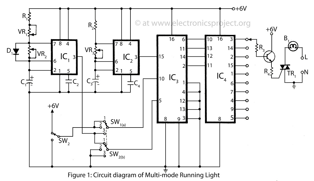
The multi-mode running light presented on this website features a simple circuit diagram designed for a bidirectional operation. It supports three different modes, making it a versatile addition to various electronics projects. The multi-mode running light circuit is designed to...
The schematic of the SAVER V3.2 is depicted in Figure 1. A transformerless power supply uses Xc of a 0.22uF capacitor to limit current, providing about 10mA current source. The diodes rectify AC current to DC current, which in...