
Light Meter Circuit

The described circuit utilizes a series of comparators to monitor an input voltage against predetermined reference voltages. The operation of the circuit is contingent upon the illumination of a photo-transistor, Q1, which serves as a light-sensitive switch. When Q1 is exposed to light, it conducts, effectively grounding the inverting inputs of the comparators. This condition ensures that the output of each comparator remains high, resulting in the associated indicator LEDs being turned off.
As the input voltage rises and surpasses the reference voltages set for each comparator, the outputs will sequentially transition from high to low. This behavior is indicative of a voltage comparator configuration where the output state changes based on the relationship between the input voltage and the reference voltage. The sequential nature of the output allows for a visual indication of the voltage level through the activation of the LEDs.
The resistors, particularly R1, play a crucial role in setting the reference voltages for the comparators. The values of these resistors must be carefully selected to ensure that the reference voltages are appropriate for the desired input voltage range. The design should also consider the characteristics of the photo-transistor, including its response time and sensitivity to light, to ensure reliable operation in varying lighting conditions.
In summary, this circuit effectively utilizes a photo-transistor and voltage comparators to provide a visual representation of voltage levels through LED indicators, enabling straightforward monitoring of input voltage variations. The outputs from the comparators will swing, in sequence, from high to low as the input voltage rises above the reference voltage applied to each comparator. The output LEDs will then switch on in sequence as the voltage rises. The inverting inputs of the comparators are connected in common to the collector of photo-transistor Ql.
When Ql is illuminated, its collec-tor-emitter junction conducts, thereby placing all the inverting inputs within a few millivolts of ground. For most settings of Rl, each of the four reference voltages exceeds the value. Therefore, when Ql is illuminated, the output from each comparator is high and its respective indicator LED is off.
Related Circuits
The circuit operates by using a clock signal to drive four D-flip-flops in the control section, which store the on/off state of each current direction for the two stepper motor coils. The flip-flops create a finite state machine (FSM)...
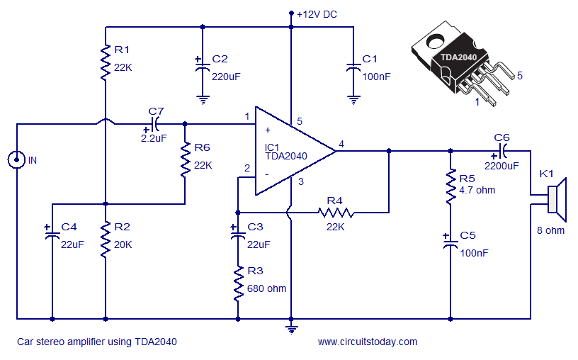
A car stereo amplifier circuit utilizing the TDA2040 is presented here. The TDA2040 is a monolithic integrated audio amplifier that functions in Class AB mode. This integrated circuit features built-in short circuit protection and thermal shutdown capabilities, and it...

A single-phase rectifier DC welding power load from the road circuit is presented. The contactor KM utilizes a CJ20-40A model rated for 220V. An adjustment potentiometer RP is employed to ensure proper arcing, while the relay KA2 is designed...
A simple thermostat circuit can be utilized to control a relay, which in turn supplies power to a small space heater via the relay contacts. It is essential that the relay contacts are rated above the current requirements for...

The power is all in the timed switching process. There are two main principles I use of switching the radiant energy the John Bedini way. First, the SG/SSG, Icehouse unidirectional circuit or John Bedini Monopole with the School Girl...
The LM1036 is a DC-controlled circuit designed for managing tone (bass/treble), volume, and balance in stereo applications, such as car radios, televisions, and audio systems. It features an additional control input for easy loudness compensation. Four control inputs allow...