
Single-phase rectifier DC welding power load from road circuit

The circuit described is a single-phase rectifier designed for DC welding applications, which converts alternating current (AC) from the road circuit into direct current (DC) suitable for welding processes. The main component, the contactor KM, is a CJ20-40A model operating at a voltage of 220V, which is responsible for controlling the power supply to the welding load. This contactor is crucial for managing the high current demands typically associated with welding operations.
In addition to the contactor, the circuit includes an adjustment potentiometer labeled RP. This component allows for fine-tuning of the arcing characteristics, ensuring that the welding arc is stable and effective. Proper adjustment of the potentiometer is vital for achieving optimal welding performance, as it influences the voltage and current characteristics during the welding process.
The relay KA2 serves as a safety and control feature within the circuit. It is designed to reliably release the load when necessary, preventing damage to the components and ensuring safe operation. The relay's activation and deactivation are critical for managing the welding cycle, allowing for precise control over the welding process.
Overall, this schematic represents a robust design for a DC welding power supply, integrating essential components that enhance performance, safety, and reliability in welding applications. The combination of the contactor, potentiometer, and relay ensures that the system operates efficiently and effectively under the demanding conditions associated with welding.Single-phase rectifier DC welding power load from road circuit is shown. Contactor KM use CJ20-40A, 220V. Adjustment potentiometer RP, ensure arcing , the relay KA2 reliable release.
Related Circuits
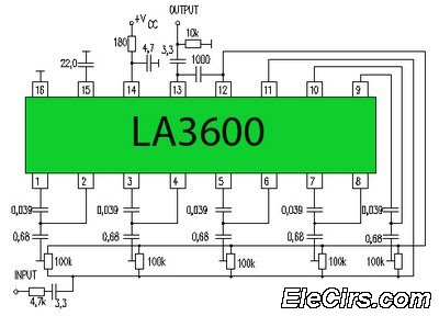
Circuit LA3600 5 Band Equalizer Circuit Schematics. One type of tone control in audio electronics is the graphic equalizer. Graphic equalizers can be categorized into two types: bar and other configurations. The LA3600 circuit is a 5-band graphic equalizer designed...
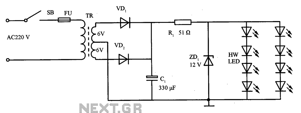
The schematic for the LED lighting circuit in a refrigerator consists of eight high-brightness white LED lights. These LEDs are housed in a transparent white plastic tube, which is the same height as the refrigerator cabinet. The circuit receives...
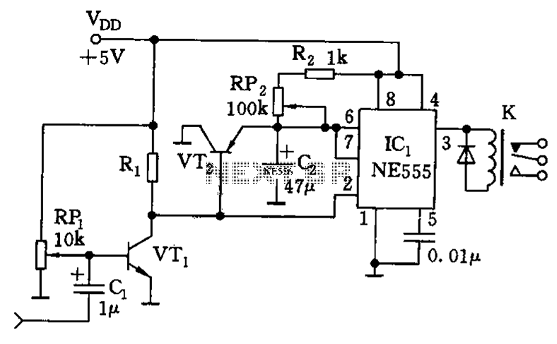
The timing circuit utilizes the 556 dual time base circuit, which includes an intermediate access N8281 crossover network. This design does not require a large volume capacitor, allowing for extended time delays. Initially, the first half of the 556...
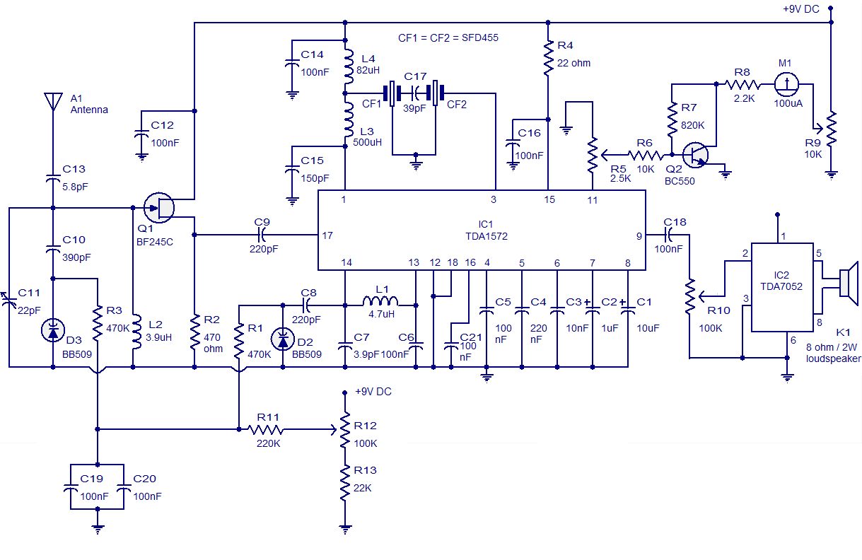
High-quality AM radio circuit based on the TDA1572 IC. The AM radio receiver circuit operates from 9V DC and has a 1W output power. It requires a minimum number of external components. The AM radio circuit utilizing the TDA1572 integrated...
The three schematics illustrate three building blocks for a 10-meter SSB transmitter. These blocks can also be utilized independently as circuit modules for other transmitters. The VFO board incorporates an FET transmission oscillator, with the VFO signal being mixed...
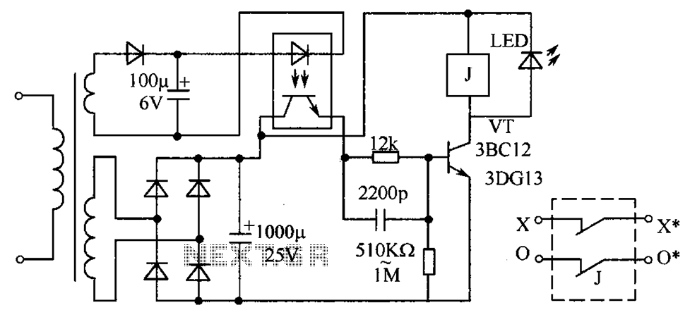
The circuit protection mechanism utilizes optocouplers for on-off control. Under normal voltage conditions, the output from the optocouplers is minimal, and the VT transistor operates in reverse bias. However, if the circuit voltage increases due to reasons such as...