
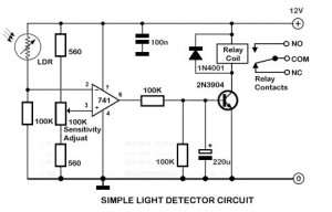
Simple Photoelectric Light Controller

The circuit utilizes a phototransistor to monitor ambient light levels. During daylight, the phototransistor remains in a conductive state, allowing current to flow through it. As the sun sets and the light diminishes, the phototransistor transitions to a non-conductive state. This change in state is critical as it allows resistor Rl to provide biasing to transistor Q2. When Q2 is activated, it triggers relay Kl, which in turn powers the connected light source, illuminating the area.
As dawn approaches and light levels increase, phototransistor Ql begins to conduct again. This conduction effectively cuts off the biasing current to Q2, leading to its deactivation. Consequently, relay Kl is also deactivated, which turns off the light. The interplay between the phototransistor and the transistors provides an automatic lighting solution that responds to environmental changes, ensuring that lights are only on when needed.
In summary, this circuit design exemplifies efficient light control through the use of a phototransistor and associated components, creating an automated system that enhances convenience and energy efficiency. A phototransistor senses daylight. At dusk, it ceases to conduct and Rl biases Q2, activates Kl, and switches on the light. At dawn, Ql starts to conduct, and Q2 is cut off. Kl drops out and the light goes out.
Related Circuits

The schematic for this project flows naturally from left to right, starting with the antenna and the regenerative receiver front-end, followed by amplification stages, and concluding with the 555 timer. This regenerative receiver front-end is commonly found in circuits...
An ambient light sensor circuit is a circuit that utilizes light intensity to perform various applications. An ambient light sensor circuit typically consists of a light-dependent resistor (LDR) or phototransistor that detects the intensity of ambient light. The sensor converts...
Alternative display methods exist beyond the original 8 LED frequency counter, potentially offering improved readability and a more suitable format for QRP equipment. This document presents examples of binary decimal displays. Typically, the counter omits the MHz position, focusing...

This circuit is a simple DC to DC converter designed for digital circuits. It operates with a supply voltage of 5V and provides an output voltage that steps up to a maximum of 10V-12V DC. The circuit utilizes an...
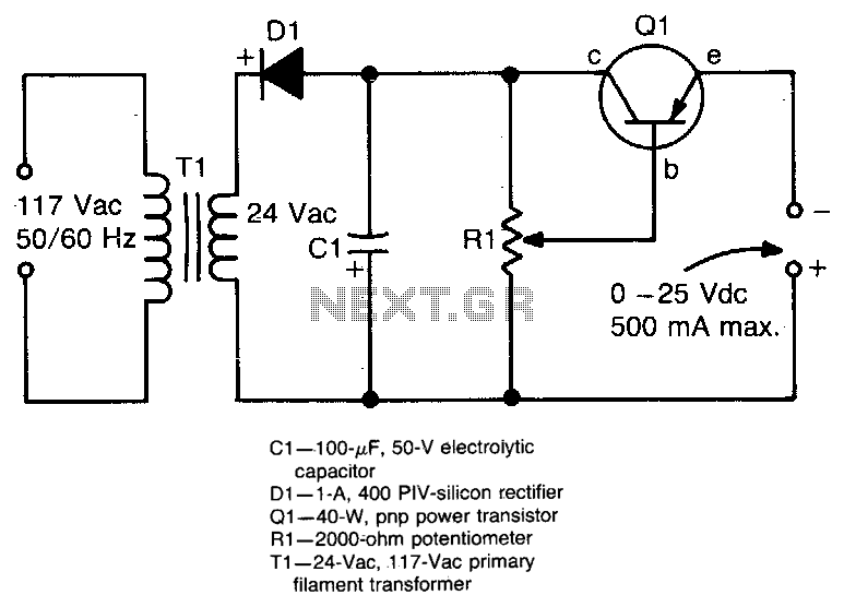
This circuit provides an adjustable output voltage of up to 35 V DC with a maximum output current of 50 mA. The transistor Q1 dissipates significant heat and must be mounted on a heatsink. The circuit in question is designed...
The NES version of this modification closely resembles the SNES version, and it is advisable to review that article first for a general understanding of the assembly of these controllers. The primary component required is an original NES controller,...