
Light Sensitive trigger

The integration of relays into a printed circuit board (PCB) design requires a clear understanding of their function and the necessary connections for both power and load management. Relays act as electrically operated switches that can control a high-power circuit using a low-power signal.
To connect the power and load correctly, the following steps should be taken:
1. **Identify Relay Specifications**: Determine the relay's coil voltage and contact ratings. This information is crucial for ensuring that the relay can handle the intended load and that the control signal matches the relay's coil requirements.
2. **Power Supply Connection**: Connect the relay coil terminals to the appropriate power supply. The positive terminal of the power supply should be connected to one coil terminal, while the other terminal connects to a control switch or microcontroller output. Ensure that the control signal voltage matches the relay coil voltage specification.
3. **Load Connection**: The load should be connected to the relay's contact terminals. Typically, a relay will have Normally Open (NO) and Normally Closed (NC) contacts. For switching applications, connect the load to the NO terminal if the load should be powered when the relay is activated. The other terminal (COM) should connect back to the power supply.
4. **Protection Circuit**: It is advisable to include a flyback diode across the relay coil terminals to protect the circuit from voltage spikes generated when the relay is de-energized. The cathode of the diode should be connected to the positive terminal of the coil.
5. **Testing the Circuit**: Once all connections are made, it is essential to test the relay operation. This can be done by activating the control signal and observing whether the load is powered as intended.
By following these guidelines, the relay can be effectively integrated into the PCB, ensuring reliable operation for controlling power to the load.I have put all the components on the PCB, now i dont know anything about relays, so i`m having trouble connecting the power and the load?.. 🔗 External reference
Related Circuits
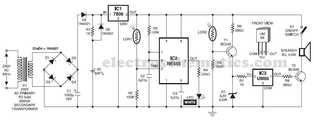
This musical light alarm circuit is very simple and uses only seven components, including a light-dependent resistor (LDR) and a 3.6V battery or three 1.2V rechargeable batteries. The well-known UM66 is utilized as the sound generator, providing a pleasant...
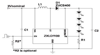
The ZXLD1100 is a PFM flyback DC to DC boost converter that operates in discontinuous mode. The following circuit diagram illustrates the configuration of four LED drivers for handset LCD backlighting using this device. The ZXLD1100 is designed to...
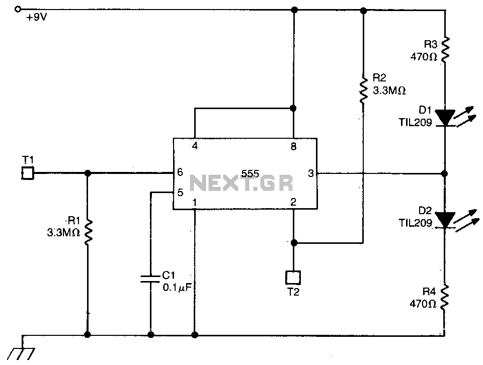
This circuit employs a 555 timer configured in bistable mode. Activating T2 results in a high output, causing D2 to conduct while D1 turns off. Conversely, activating T1 leads to a low output, with D1 conducting and D2 being...
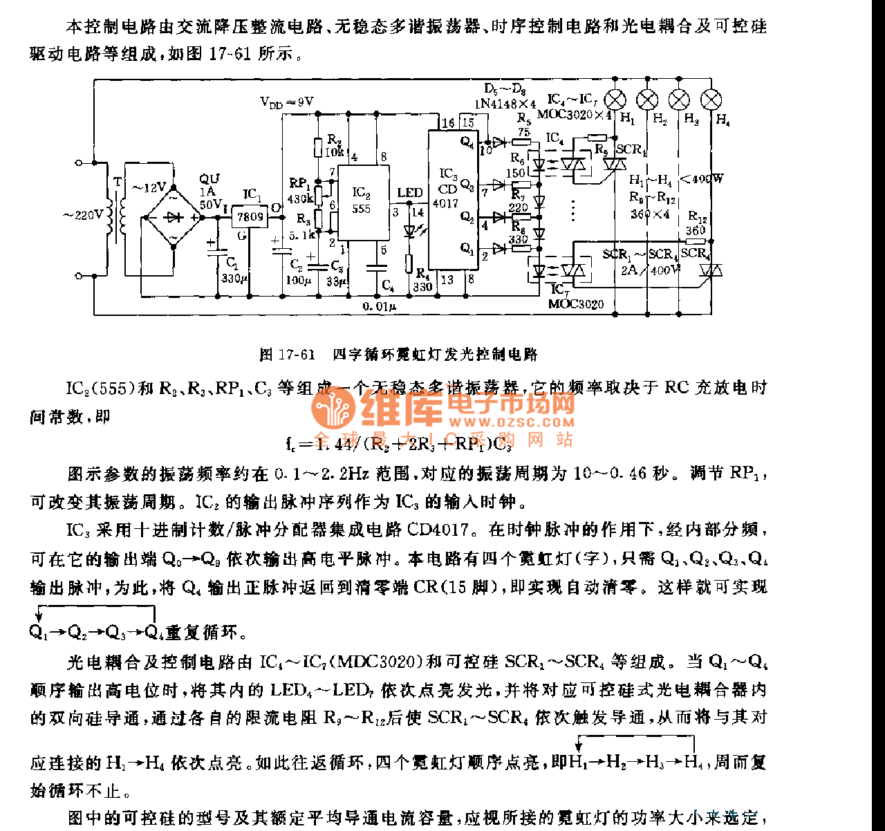
This control circuit consists of an AC step-down rectifier circuit, an astable multivibrator, a timing control circuit, an optocoupler circuit, and an SCR driving circuit, as illustrated in Figure 17-61. The astable multivibrator is formed using IC2 (555), resistors...
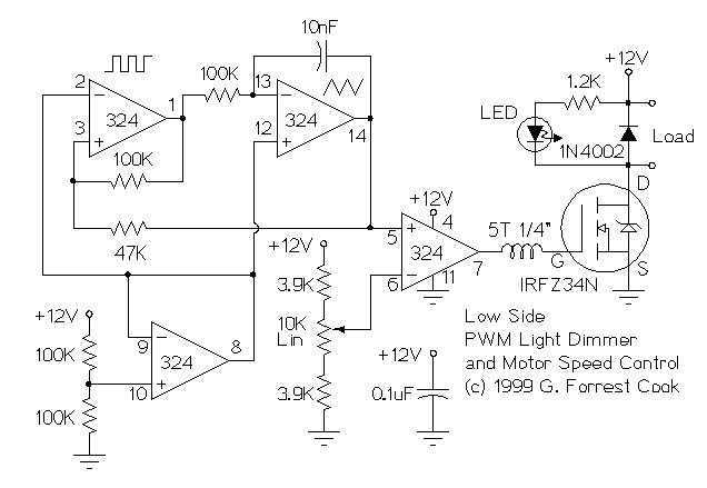
These two schematics are variations on another PWM circuit that I designed. The diagrams are for 12V operation only and there are high side (common ground) and low side (common +12V) versions. The low side version of the circuit...
Sun tracking systems significantly enhance the efficiency of photovoltaic (PV) arrays and are crucial for concentrated PV systems. This document discusses a light tracking servo model designed to simulate the movement of a PV array. A mathematical model is...