
555 four words cycle neon light light control circuit

The control circuit is designed to convert AC voltage to a lower DC voltage using the step-down rectifier circuit, which typically employs a transformer and a bridge rectifier to achieve this function. The output of the rectifier feeds into the astable multivibrator, which generates a continuous square wave signal. This multivibrator configuration utilizes the 555 timer IC, known for its reliability and versatility in timing applications. The frequency of the output signal from the astable multivibrator is influenced by the values of the resistors R2, R3, and RP1, as well as the capacitor C3. The relationship between these components defines the time constant, which is crucial for determining the oscillation frequency.
Following the astable multivibrator, the timing control circuit may include additional components such as diodes and capacitors to manage the timing intervals and ensure stable operation. The optocoupler circuit serves to isolate different sections of the circuit while allowing signal transfer, enhancing safety and reducing noise interference. The SCR driving circuit is responsible for controlling the power to the load, utilizing silicon-controlled rectifiers to switch the load on and off based on the control signals received from the preceding circuits.
Overall, this control circuit is designed for applications requiring precise timing and control of AC loads, ensuring efficient operation and reliable performance in various electronic systems.This control circuit is composed of the AC step-down rectifier circuit, the astable multivibrator, the timing control circuit, the optocoupler circuit and the SCR driving circuit.etc. As the figure 17-61 shows. The astable multivibrator is composed of the IC2(555) and R2?R3?RP1?C3.etc. It`s frequency depends on RC`s charging and discharging time constant, f.. 🔗 External reference
Related Circuits
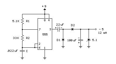
A 555 timer can be used to generate a square wave to produce a negative voltage relative to the negative battery terminal. When the timer output at pin 3 goes positive, the series 22 uF capacitor charges through the...
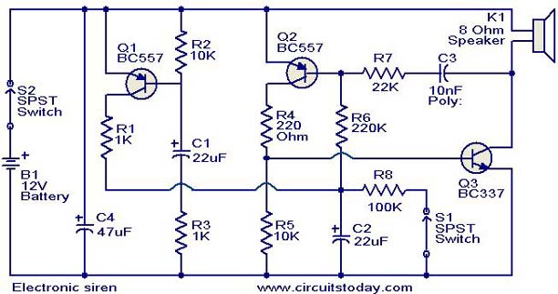
This is a compact electronic siren circuit based on three transistors. This circuit is suitable for incorporation with other alarm or siren projects such as burglar alarms, automatic factory sirens, or a simple push-to-on alarm. The electronic siren circuit...
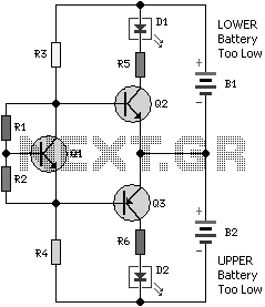
Almost all 24V power systems in trucks, 4WDs, RVs, boats, etc., utilize two series-connected 12V lead-acid batteries. The charging system can only sustain the total voltage of the individual batteries. If one battery is failing, this circuit will illuminate...

The TVT-MOBI-2 will initially display a static image and will not respond to data from its serial interface, except for one function. The internal clock can be set by providing a date and time value, allowing it to calculate...
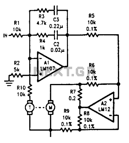
The tachometer, mounted on the same shaft as the DC motor, functions as a generator, producing a DC output voltage that is proportional to the motor's speed. A summing amplifier, labeled as Al, manages its output to ensure that...
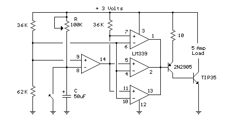
In this circuit, an LM339 quad voltage comparator is used to generate a time delay and control a high current output at low voltage. Approximately 5 amps of current can be obtained using a couple of fresh alkaline D...