
light sensor circuit using pic16c63

This light sensor circuit is designed to interface a photosensor with electronic components, effectively bridging the gap between optical signals and electronic processing. The core of the circuit comprises an operational amplifier (op-amp) and the PIC16C63 microcontroller, which collectively manage the control of the photosensor. The circuit is not optimized for high-precision applications; however, it is well-suited for positional photo sensing applications where stability issues associated with amplifiers are minimized.
The architecture allows for the integration of a programmable gain amplifier (PGA) with multiple channels—specifically two, six, or eight channels. This design flexibility enables the incorporation of additional sensors or arrays of photosensors without the need for extra signal conditioning hardware or increased consumption of I/O pins on the PIC microcontroller. Such a setup is advantageous in complex systems where multiple inputs are required, as it maintains efficiency in both hardware and software.
The circuit utilizes a multiplexer paired with a high-speed conversion response from the PGA to ensure that the photosensor input signal can be sampled and converted to the digital domain swiftly. The use of the Serial Peripheral Interface (SPI) allows seamless communication between the PIC16C63 microcontroller and the PGA, facilitating rapid channel switching. This feature is critical in applications where real-time data acquisition is necessary.
The PGA can be configured for different settings with the photosensor, accommodating a range of signal responses from direct current (DC) to frequencies of approximately 100 kHz. This versatility makes the circuit suitable for various applications in light sensing and monitoring, allowing for effective signal processing and data interpretation in electronic systems.This light sensor circuit that is photos sensor is the gap between light and electronics. This circuit is built by op amp and microcontroller PIC16C63 for control the sensor. This circuit is not precision application, but they can be effectively used in position photo sensing applications minus the headaches of amplifier stability. This is the fig ure of the circuit. When the two, six or eight channel PGA is used in this system, the other channels can be used for other sensors or an array of photo sensors without an increase in signal conditioning hardware or PIC micro ® microcontroller I/O pin consumption. The multiplexer and high-speed conversion response of the PGA / Analog-to-Digital (A/D) conversion allows the photo sensor input signal to be sampled and quickly converted to the digital domain.
Switching from channel to channel is then easier with the Serial Peripheral Interface (SPI) from the PIC16C63 microcontroller to the PGA. The PGA can be configured with a photo sensor in two different settings. These circuits are appropriate for signal responses from DC to ~100 KHz. [Schematic circuit source: Microchip Technology, Inc] 🔗 External reference
Related Circuits
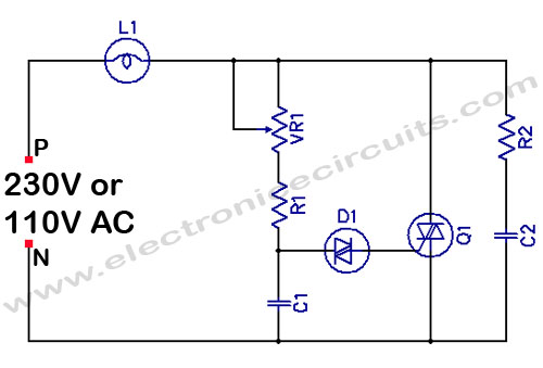
Filament Light Dimmer Circuit. This simple triac dimmer can be used to control incandescent filament lamps up to 200W. The circuit operates on standard AC voltage. The filament light dimmer circuit utilizes a TRIAC to control the power delivered to...
The documents, software, tools, and links are provided to enhance the capabilities of electronics students, hobbyists, or professionals by sharing information. This information and the associated links should be utilized by website visitors at their own risk and responsibility....
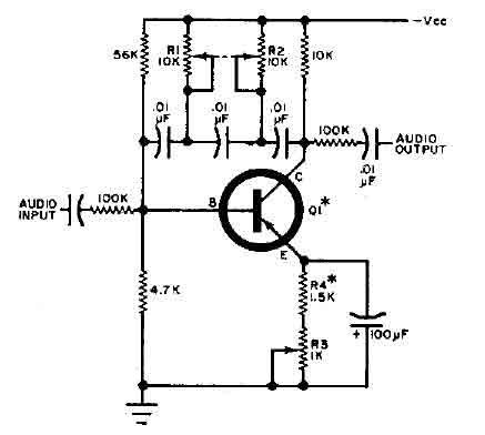
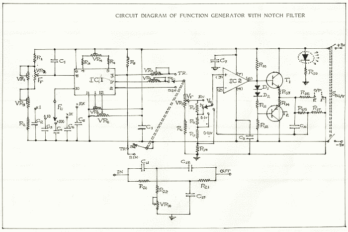
This circuit is designed for selective tuning adjustments between two closely spaced audio tones. The frequency is determined by the values of the capacitors and resistors in the feedback circuit connecting the collector and base of transistor Q1. With...
This simple circuit tests speakers, microphones, transformers, and voltage. It is essentially a very low-frequency oscillator that produces extremely short pulses. The sound produced is easy to hear and helps determine the precise direction it originates from, making it...
Involvement is a modified version of the classic circuit of automatic level control signal used in tape recorders. The purchase price of the components (using TL072) does not exceed CZK 60 for a channel. For a range of entry...
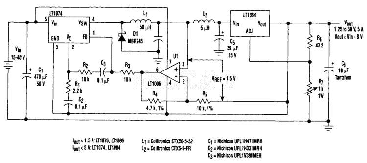
Large input-to-output voltage differentials, caused by wide input voltage variations, reduce a linear regulator's efficiency and increase its power dissipation. A switching preregulator can reduce this power dissipation by minimizing the voltage drop across an adjustable linear regulator to...