
Filament Light Dimmer Circuit

The filament light dimmer circuit utilizes a TRIAC to control the power delivered to incandescent lamps. The primary components include a TRIAC, a diac, resistors, and capacitors arranged to form a phase control circuit. The TRIAC acts as a switch that regulates the amount of current flowing to the lamp, allowing for a dimming effect.
When the circuit is powered, the diac remains non-conductive until the voltage across it reaches a certain threshold. Once this threshold is exceeded, the diac conducts, triggering the TRIAC. The timing of the TRIAC's conduction is controlled by the RC timing network, which determines at which point in the AC cycle the TRIAC will turn on. By adjusting the resistance or capacitance in this network, the phase angle at which the TRIAC begins to conduct can be varied, thus controlling the brightness of the lamp.
This circuit is suitable for applications where dimming capabilities are desired, such as in residential lighting or decorative fixtures. It is essential to ensure that the TRIAC is rated for the appropriate load current and voltage, and that adequate heat sinking is provided to dissipate any heat generated during operation. Additionally, proper isolation and safety measures should be implemented to prevent electrical hazards.
The design is straightforward and can be implemented on a PCB or a breadboard for prototyping. Careful attention should be paid to component placement to minimize noise and interference, ensuring stable operation of the dimmer circuit.Filament Light Dimmer Circuit This simple triac dimmer can be used to control incandescent filament lamps up to 200W. The circuit operates on.. 🔗 External reference
Related Circuits
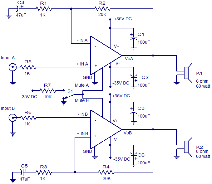
The circuit diagram presented is for a 2 x 60 Watt stereo amplifier utilizing the LM4780 from National Semiconductors. The LM4780 is an excellent audio amplifier integrated circuit capable of delivering 60W RMS power output per channel into 8-ohm...
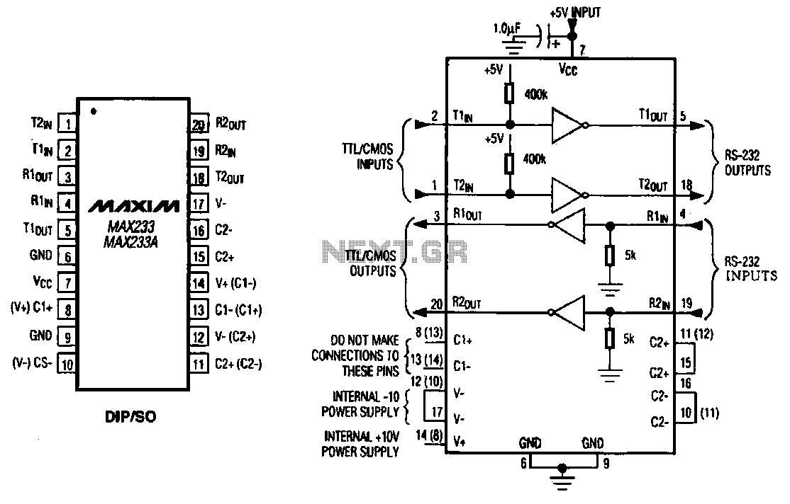
The MAX233 / 233A is a multi-channel data interface circuit featuring dual output and dual input driver circuits. It is designed for small digital products and multimedia equipment to facilitate data transmission. The MAX233 / 233A integrates multiple functions to...
When the door is opened, SW1 closes, powering the circuit and turning on the lamp. C1 begins to charge slowly through R1, and when the voltage at pins #2 and #6 of IC1 reaches 2/3 of the supply voltage,...
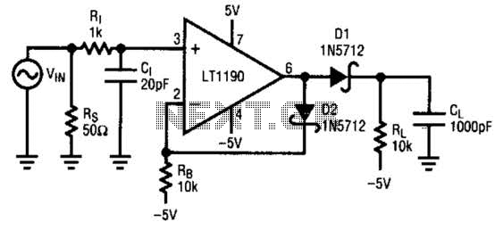
A fast pulse detector can be constructed using this circuit. A very fast input pulse will surpass the amplifier's slew rate, resulting in a prolonged overload recovery time. Implementing some degree of dv/dt limiting on the input can alleviate...
Hello everyone. I need some help. I have constructed a PWM and PPM circuit. The output is functioning smoothly, but I am experiencing some problems and I am not very experienced. The PWM (Pulse Width Modulation) and PPM (Pulse Position...
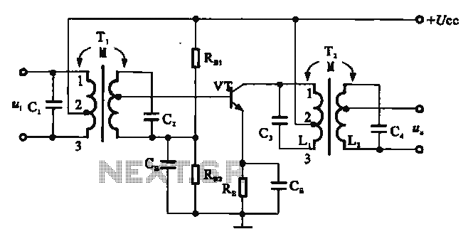
There are two resonant circuits in a double-tuned amplifier circuit, which consists of transformers T1 and T2 with primary and secondary coils that include parallel resonance capacitors. This circuit exhibits a resonance function and can be classified based on...