
Q-multiplier filter circuit

The circuit operates by utilizing a feedback mechanism that allows for fine-tuning of audio frequencies. The key component, transistor Q1, acts as an amplifier, where the feedback loop formed by the resistors and capacitors enhances the selectivity of the circuit. The capacitors determine the resonant frequency, while the resistors influence the gain and bandwidth of the response.
The three potentiometers serve a critical role in adjusting the circuit's response characteristics. By manipulating these potentiometers, the user can modify the sharpness of the response curve, which is essential for achieving the desired audio clarity and separation between the closely spaced tones. This level of control is particularly useful in applications such as audio processing, signal filtering, and tone generation.
To implement this circuit, careful selection of component values is crucial. The resistors and capacitors must be chosen to match the desired frequency response and tuning range. Additionally, proper layout and grounding techniques should be employed to minimize noise and interference, ensuring optimal performance of the circuit. The overall design should be tested and calibrated to verify that it meets the required specifications for audio applications.This circuit is selective for the tuning adjustment between two closely spaced tones audio. The frequency is dependent on the selective value capacitors and resistors in the feedback circuit between the collector and base of Q1. With the values shown, the frequency can be tuned to a hundred cycles or so-around 650 Hz Ri and R2 should be grouped.
R 3 potentiometer transmitter determines the sharpness of the response curve. Source: discovercircuits 🔗 External reference
Related Circuits
TCRT1000 - Reflective Optical Sensor manufactured by Vishay Semiconductors. This component was ordered from Mouser. For more information, refer to the Sensor Report on the Reflective Optical Sensor TCRT1000. While there are concerns regarding the code and schematic used,...
This circuit is designed to support nine independent telephones using a single telephone line pair, allowing for operation at nine different locations. It includes a bidirectional telephone line simulator that does not require actual telephone lines, enabling the coupling,...
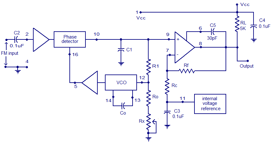
A simple PLL FM demodulator circuit using the IC XR2212 is presented. The XR2212 is a highly stable, monolithic PLL (phase-locked loop) IC specifically designed for communication and control system applications. It operates within a frequency range of 0.01...
The circuit comprises a 3-stage resistor-capacitor coupled amplifier. When ring button S2 is pressed, the amplifier circuit formed around transistors T1 and T2 gets converted into an asymmetrical astable multivibrator generating ring signals. These ring signals are amplified by...
How to create a hydrogen generator using a 555 timer circuit with Pulse Width Modulation (PWM). This PWM circuit can generate hydrogen on demand. The hydrogen generator circuit utilizing a 555 timer operates by controlling the duty cycle of the...
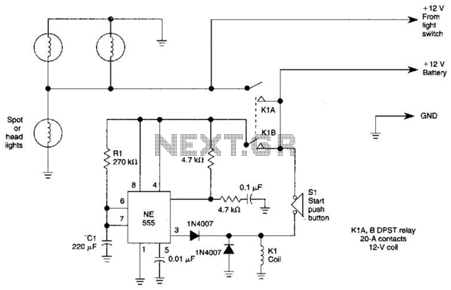
Pressing the START pushbutton activates either the headlights or spotlights for a specified duration. After 1 minute, determined by R1 and C1, the lights will turn off as the NE555 timer completes its cycle. The circuit utilizes a NE555 timer...