
Light Sequencer schematic

Assuming the circuit does not start when power is applied and all lights are off with all three capacitors charged to approximately 5 volts, a jumper can be connected across the 220µF capacitor on the left. This action discharges the capacitor, turning on the second stage transistor and the corresponding light. Once the jumper is removed, the capacitor will begin to charge through the base of the stage 2 transistor and the stage 1 light. This charging process allows the stage 2 transistor to remain in the 'on' state while the capacitor continues to charge.
Simultaneously, the capacitor connecting stage 2 and stage 3 will discharge through a 100-ohm resistor and a diode, as well as through the stage 2 transistor. When the charging current through the capacitor falls below the threshold needed to keep stage 2 activated, the transistor and its associated light will turn off. This action causes the voltage at the collector of the stage 2 transistor to rise back to 5 volts. As the capacitor connecting stages 2 and 3 has discharged, the increase in voltage at the collector of the stage 2 transistor allows the capacitor from stage 2 to stage 3 to charge, thereby turning on the third stage and continuing the cycle for subsequent stages (4, 5, 6, 7, etc.) and eventually returning to stage 1.
The sequence rate of this light sequencer is determined by the values of the capacitors and resistors used (220µF and 100 ohms in this configuration), the load current (200mA), and the current gain of the specific transistors employed. This arrangement is capable of achieving approximately 120 complete cycles per minute for the three lights, translating to a duration of about 167 milliseconds per light. Adjusting the capacitor values can yield faster or slower sequencing rates, allowing for customization based on specific application requirements.The drawing below illustrates a multistage light sequencer using descrete parts and no integrated circuits. The idea is not new and I hear a similar circuit was developed about 40 years ago using germanium transistors.
The idea is to connect the lights so that as one turns off it causes the next to turn on, and so forth. This is accomplished with a large capacitor between each stage that charges when a stage turns off and supplies base current to the next transistor, thus turning it on.
Any number of stages can be used and the drawing below illustrates 3 small Christmas lights running at about 5 volts and 200mA. The circuit may need to be manually started when power is applied. To start it, connect a momentary short across any one of the capacitors and then remove the short. You could use a manual push button to do this. Detailed operation: Assume the circuit doesn't start when power is applied amd all lights are off and all three capacitors are charged to about 5 volts. We connect a jumper across the 220uF capacitor on the left which discharges the capacitor and turns on the 2nd stage transistor and corresponding light.
When the jumper is removed, the capacitor will start charging through the base of the stage 2 transistor and stage 1 light. This causes the stage 2 transistor to remain on while the capacitor continues to charge. At the same time, the capacitor connecting stage 2 and 3 will discharge through the 100 ohm resistor and diode and stage 2 transistor.
When the capacitor charging current falls below what is needed to keep stage 2 turned on, the transistor and light will turn off causing the voltage at the collector of the stage 2 transistor to rise to 5 volts. Since the capacitor connecting stage 2 and 3 has discharged and the voltage rises at the collector of stage 2, the capacitor from stage 2 and 3 will charge causing the 3rd stage to turn on and the cycle repeats for sucessive stages 4,5,6,7....
and back to 1. The sequence rate is determined by the capacitor and resistor values (220uF and 100 ohms in this case), load current (200mA in this case), and current gain of the particular transistor used. This arrangement runs at about 120 complete cycles per minute for 3 lights, or about 167mS per light.
Faster or slower rates can be obtained with different capacitor values. 🔗 External reference
Related Circuits
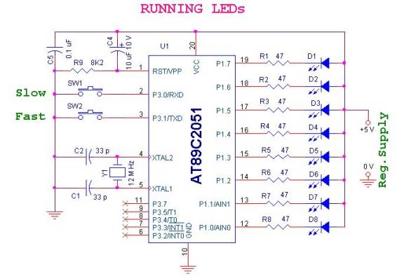
The circuit is simple and straightforward. Two inputs are included to demonstrate input control and software debouncing. An ATMEL microcontroller AT89C2051 is utilized to control the sequential glowing of LEDs, creating a running light effect. A 12 MHz crystal...
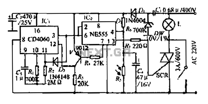
A photosensitive daytime electricity circuit utilizes a very small positive voltage. It features a 555 timer IC with four pins, including a reset pin that operates at low voltage. The circuit includes a bidirectional thyristor (iSCR) that controls lighting,...
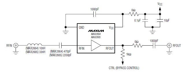
A simple, low-cost, and ultra-compact VHF/UHF low-noise amplifier circuit can be designed using the MAX2664 and MAX2665 ultra-compact LNAs for VHF/UHF applications. These devices incorporate a broadband LNA with an integrated bypass switch. The MAX2664 covers the UHF frequency...
The following circuit illustrates the CD4017 integrated circuit (IC) used in an automatic room lights sensor circuit diagram. Features include a single light sensor utilizing two light-dependent resistors (LDRs). The CD4017 is a decade counter IC that can drive multiple...
Many individuals use headphones connected to a computer sound card output to enjoy music or games. It is common for these headphones and microphones to connect to the appropriate slots on the sound card. However, if the female plug...
With this circuit we can change the brightness of lamb, with a only key of touch. The key of touch is connected in the circuit, center of which is a special completed IC1, which is the S566B of SIEMENS....