
Light timer switch with PIC12F629

The lamp timer circuit is designed to control two relay switches, allowing for versatile operation modes: OFF, delayed ON, and constant ON. It utilizes a microcontroller, specifically the PIC12F629, although it can be adapted for use with other microcontrollers such as the PIC16F628 or OTP 12C508. The microcontroller interfaces with the relay switches to control the lamp based on user input.
The operation of the timer is facilitated through a single push-button interface. The user can initiate the lamp operation by pressing the button once, which activates the lamp for a pre-defined delay period. During this period, pressing the button again will switch the lamp to a constant ON state, effectively disabling the delay timer. A subsequent press of the button will turn the lamp OFF.
If the constant ON mode is disabled, the operation changes slightly: pressing the button once will again turn on the lamp for the specified delay. However, pressing the button a second time will turn the lamp OFF instead of switching it to constant ON.
The source code for this application is available for download and is designed to be easily customizable. Users can modify the delay times to suit their specific requirements. Notably, the timing mechanism is constrained by the limitations of the microcontroller's bit addressing; 30 minutes cannot be represented within a 16-bit integer. To overcome this limitation, the clock frequency can be increased to 12 MHz, allowing for the default delay values (dly_a and dly_b) to be set to 9 and 30 minutes, respectively. The timing is measured in 30 ms increments instead of the standard 10 ms, providing a more accurate representation of longer delay periods.
This circuit is suitable for applications where timed control of lighting is necessary, providing users with flexibility in operation while maintaining simplicity in design.This is a lamp timer capable of operating two separate relay switches. Outputs can be in three (or restricted to two) states: OFF, delayed ON and constant ON. Delayed ON mode is indicated by the LEDs. The source code is easily customizable for your needs: set your desired delay time or disable constant ON state. press the button once to turn on the lamp for a pre-defined delay. while ON, press the button again to turn the lamp constant ON (turn off delay timer). press the button again to turn the lamp OFF. alternative operation, if you disable the constant ON mode: press the button once to turn on the lamp for a pre-defined delay.
while ON, press the button again to turn the lamp OFF. The source code is freely downloadable. This is written for the PIC12F629, but you can easily adapt it to other controllers like the 16F628 or OTP 12C508. The problem is that 30 minutes don't fit into 16 bits. The simplest solution is to increase MHZ to 12, so for the default dly_a, dly_b values you get 9 and 30 mins (the values specified get measured in 30ms instead of 10ms).
🔗 External reference
Related Circuits
The circuit of the mains current detector is shown in Figure 1. By using a few cheap diodes, a resistor, LED and LDR, a simple opto-isolated detector can be created. This entire circuit dissipates very low power, and can...
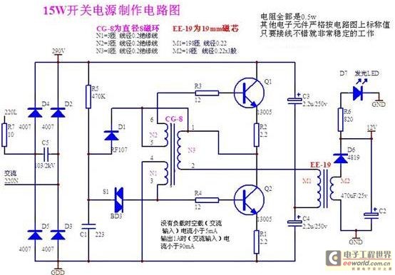
A daily switching power supply primarily provides direct current (DC) power to electronic devices. The required DC voltage for electronic devices typically ranges from several volts to over ten volts, while the input voltage from the mains supply is...
The ADP1864 is a compact, cost-effective, constant-frequency current-mode step-down DC-DC controller. It drives a P-channel MOSFET to regulate an output voltage as low as 0.8 V with ±2% accuracy, handling load currents up to 5 A from input voltages...
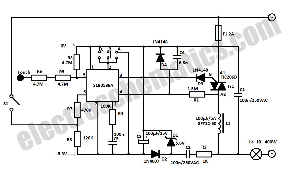
The SLB0586A integrated circuit from Siemens can be utilized to create a simple touch light dimmer circuit, allowing for the adjustment of lamp intensity. When paired with a TIC206D triac, this setup enables smooth regulation of light intensity for...
This is a capacitor power supply. This is a very small current of energy-effective because it has very little loss, much smaller than the miniature transformer. Capacitor impedance is inversely proportional to frequency. This is a great disadvantage when...
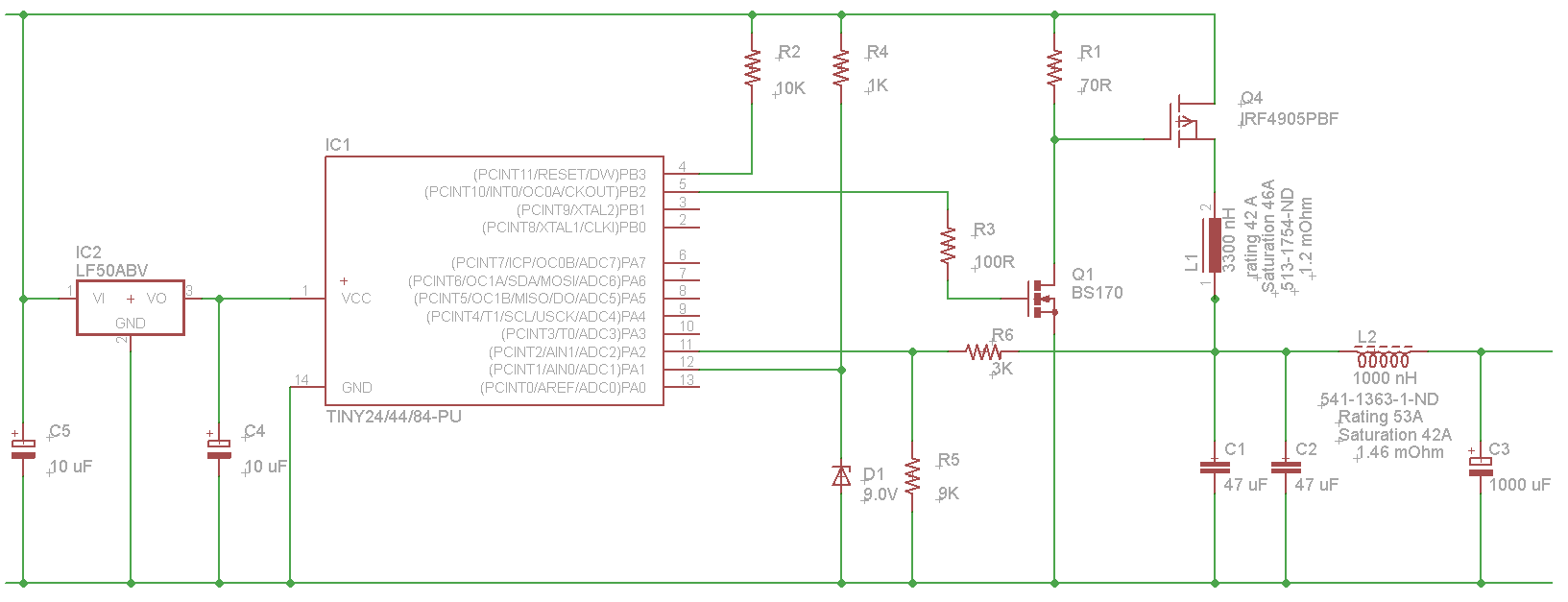
The microcontroller will not be able to drive the gate of Q1 effectively, as GPIO pins typically can only source a few milliamps, resulting in slow turn-on and turn-off times. This limitation will affect the performance of the high-side...