
Light to Frequency converter

The light-to-frequency converter circuit is designed to convert varying light intensities into corresponding frequency signals, facilitating the measurement of light levels. The circuit employs the TLC555 timer IC, which operates in an astable mode to generate a square wave output whose frequency is proportional to the input light intensity.
The primary components of the circuit include the TLC555 timer IC, a photodetector (such as a photodiode or phototransistor), resistors, and capacitors. The photodetector captures the incoming light and produces a current proportional to the light intensity. This current is fed into the TLC555, which is configured to convert the current signal into a frequency output.
In the astable mode of operation, the TLC555 continuously switches between its high and low states, producing a square wave. The frequency of this output is determined by the values of the timing resistors and capacitor connected to the IC. The relationship between the light intensity and the output frequency can be adjusted by selecting appropriate resistor and capacitor values, allowing for calibration based on specific measurement requirements.
The schematic diagram typically shows the TLC555 connected with the photodetector and timing components. It is essential to ensure proper connections and component values for accurate light intensity measurement. This circuit can be applied in various applications, including ambient light sensing, automatic lighting systems, and scientific experiments that require precise light intensity monitoring.A simple light to frequency converter circuit with diagram and schematic.Used as Light intensity measurement circuit.Design using TLC555, a cmos version of NE 555 timer IC.. 🔗 External reference
Related Circuits
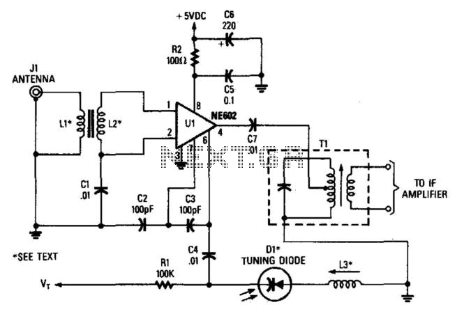
In this configuration, the NE602 serves as a frequency converter in a superheterodyne front-end setup. L1 and L2 form a broadband toroidal transformer, although a tuned transformer may also be utilized. The supply voltage ranges from +5 to +9...
The following governor is designed to regulate the light intensity of a 220 V incandescent lamp. The circuit consists of relatively few components, allowing for easy assembly on a small circuit board. It is recommended to enclose the completed...
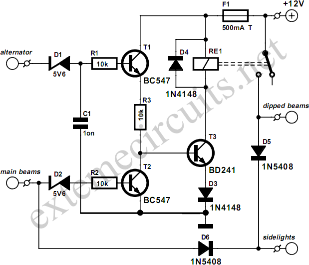
This circuit ensures that the car's lights will automatically activate when the engine is running, preventing the driver from forgetting to turn them on. The dipped beams and sidelights are engaged automatically, while the dipped beams turn off when...
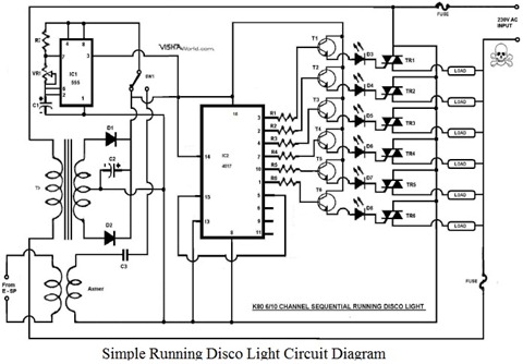
This article explains how to design a minimal Running Disco Light Circuit Diagram using the IC 4017. The IC 4017 is a 16-pin dual in-line package integrated circuit that includes a 10-stage decade counter. The design operates on 230V...
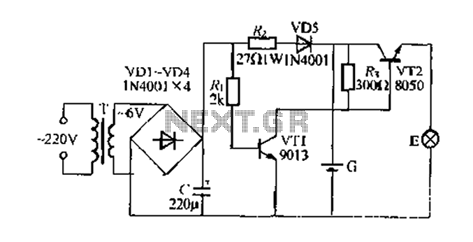
Figure 282 illustrates a simple emergency lamp circuit designed to activate during a power outage. The circuit utilizes a transformer (T) for voltage stepping, diodes (VD1 to VD4) for rectification, and a capacitor (C) for smoothing the output. During...

R4 prevents the output voltage from drifting toward one of the supply rails of the operational amplifier. It is understood that R4 should have a high resistance, although the reason for this is unclear. The schematic appears to be...