
Lights On!

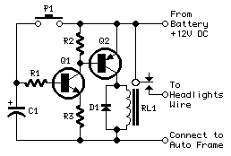
The circuit operates as follows: Upon starting the engine, the alternator generates a voltage greater than 14 V. This voltage is routed through diode D1, which drops it to 5.6 V, suitable for driving transistor T1. Resistor R1 limits the current into T1's base, ensuring it operates within safe parameters. Once T1 is activated, it allows current to flow through R3, providing a base current for T3. This results in T3 turning on, which energizes relay Re1, closing its contacts and powering the dipped beams and sidelights.
When the driver activates the main beams, current flows through diode D2 and resistor R2, energizing transistor T2. This action decreases the voltage at T3's base, causing it to turn off and de-energizing relay Re1, which in turn extinguishes the dipped beams. The system is designed to revert to its original state when the main beams are switched off, allowing the dipped beams and sidelights to operate once again.
The inclusion of diodes D5 and D6 ensures that the sidelights are illuminated whenever either set of beams is engaged, providing a safety feature that enhances visibility. This design is straightforward, requiring only common components, which simplifies installation and reduces cost while ensuring reliable operation of the vehicle's lighting system.This circuit ensures that you will never again forget to switch on the lights of your car. As soon as the engine is running, the dipped beams and the sidelights are automatically switched on. The circuit also causes the dipped beams to be extinguished as soon as the main beams are switched on. As you can see from the schematic diagram, no special components are needed. When the engine is running, the alternator will generate a voltage of more than 14 V. Diode D1 reduces this voltage by 5. 6 V and passes it to the base of T1 via R1. Due to the resulting current, T1 conducts. The amplied current‚ows via R3, the base of T3 and D3 to ground. This causes T3 to also conduct and energize relay Re1. If the driver now switches on the main beams, a current‚ows through D2 and R2 into the base of T2, causing this transistor to conduct. As a result, the voltage on the base of T3 drops, causing T3 to cut off and the relay to drop out. When the main beams are switched off, the previous situation is restored, and the relay again engages.
The dipped beams and the sidelights are switched by the contacts of relay Re1. Diodes D5 and D6 ensure that the sidelights are illuminated if either the dimmed beams or the main beams are switched on. In practice, this means that the sidelights will be on whenever the engine is running, regardless of whether the main beams are switched on.
🔗 External reference
Related Circuits
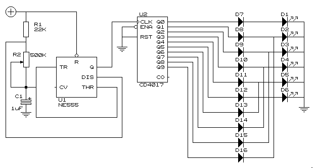
This circuit operates six LEDs in a "Knightrider scanner mode." The power consumption is primarily influenced by the type of LEDs utilized, especially when employing a 7555 (CMOS version of the 555 timer). Caution is advised when working with...
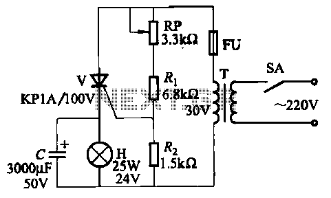
The circuit employs thyristor control. The flash frequency is determined by resistors Ri, RP, Rz, and capacitor C. By adjusting the electrical locator RP, the flash frequency can be varied from 0.5 Hz to several Hz. The described circuit utilizes...
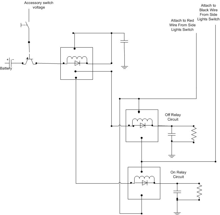
A decision has been made to install daytime driving lights for an Elise vehicle. The intention is to eliminate the need for manually pressing the button on and off repeatedly. The installation of daytime driving lights (DRLs) enhances vehicle visibility...
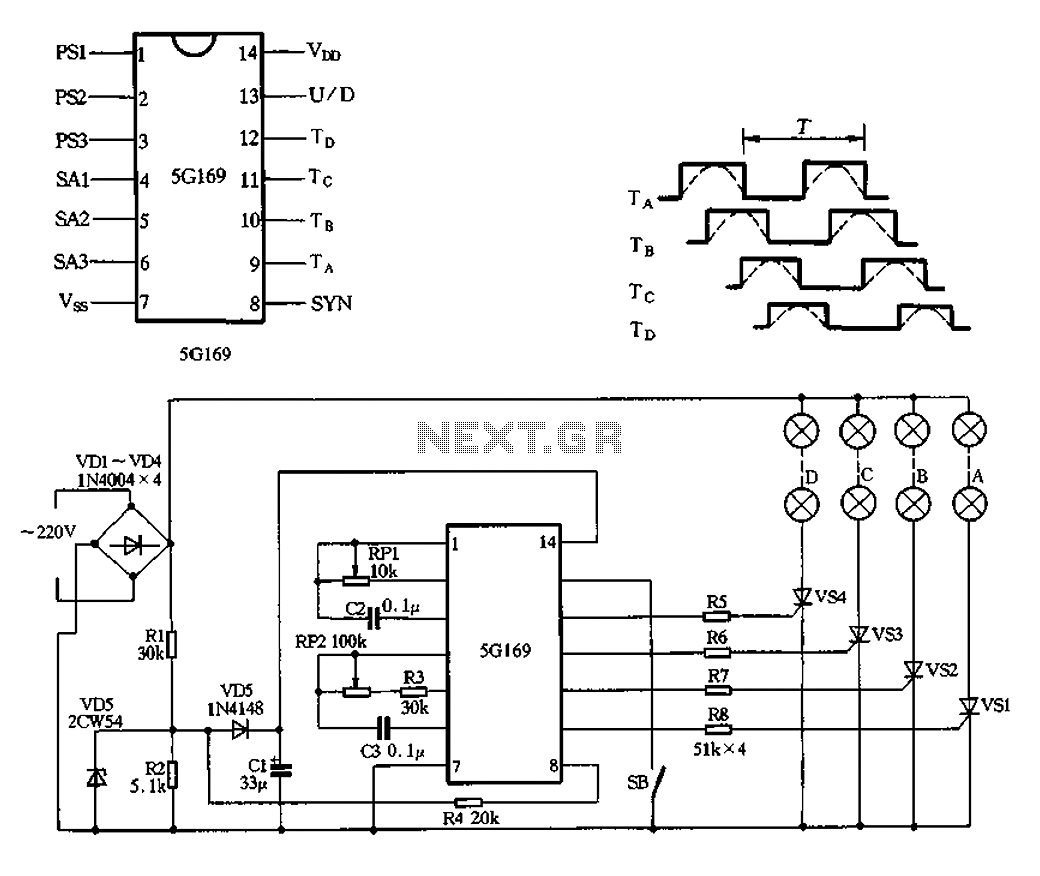
The circuit features an AC input from VDI, which is converted to pulsating DC power using a VD4 full-wave bridge rectifier to power four lights. Resistors R1 and R2, along with diode VD5, form a simple circuit, while VD6...
This device is a simple timer that keeps the headlights of a vehicle illuminated for approximately 1 minute and 30 seconds. This feature is particularly useful when accessing dark areas, eliminating the need to return to manually switch off...
An emergency light is a light source designed to be available during emergencies. It operates automatically and is powered by a rechargeable battery. An emergency light system typically consists of several key components: a light source, a rechargeable battery, a...