
Light touch variable delay circuit

The circuit described utilizes a silicon controlled rectifier (SCR) to control the lighting based on touch input. The absence of a base current indicates that the circuit is designed to operate in a low-power state until activated. When the metal sheet is touched, it triggers a change in the state of the circuit, allowing the capacitor to charge. The charging process is time-dependent, with the capacitor reaching a voltage of 2V.
The SCR is a key component that allows for the conduction of current when triggered by a direct current (DC) voltage. The circuit's design incorporates ten essential components, which may include resistors, capacitors, diodes, and the SCR itself. The continuous discharge of the circuit is a critical feature, as it ensures that the lights remain off when the metal contact is established.
The interaction between the touch input and the circuit's voltage dynamics is significant. A brief touch increases the voltage across the circuit, leading to a shorter duration of light activation. Conversely, a prolonged touch results in a higher charging voltage, which extends the delay before the lights turn off. For instance, a one-second touch can produce a charging voltage of 5V with a delay of 100 seconds, while a two-second touch yields a charging voltage of 7.5V and a delay of 140 seconds. A three-second touch increases the charging voltage further to 10V, with a 15-second delay before the lights extinguish.
This behavior exemplifies the circuit's sensitivity to touch duration, allowing for a customizable lighting experience based on user interaction. The theoretical calculations supporting this design provide insight into the expected performance and operational parameters, ensuring reliability and efficiency in its application.vl.U no mantle base current. Open cut II:, n is also turned off when the touch when the metal sheet. CI JF start charging. Lu Ci Bu l: charge to 2V Tsui l: time. V, Chong: im, generating Rs L DC dirty drop trigger pull bite silicon SCR conduction, the lights. It consists of ten C. The more people who ask constant discharge, open extension l column Duan Yan lights off when M. When you touch the metal "M I little while when the voltage across the electrical .q TV Division, touch steamed shabu li inch shorter, lower C, both ends of the voltage discharge M also girl, so electric lights time is short, and vice versa r cancer when I change may K. So Shing touch setback time delay n.rriil_ boots close by varying widely cited theoretical calculation, when touch hug one second, ' a charging voltage of 5v, delay IOO seconds; 2 seconds touch Ut, CI charging voltage is 7.5v.
delay l40 seconds, 3 seconds break contact resistance, cl charging voltage IOV. la5 seconds delay.
Related Circuits
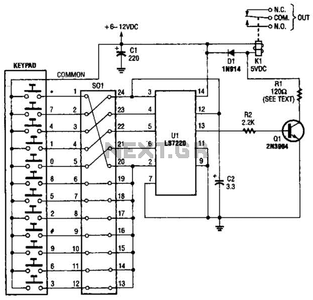
A block pinout diagram of the LS7220 keyless-lock IC is presented. The keypad must provide each key with a contact to a common connection. In this instance, the common connection is linked to the positive supply rail, allowing a...
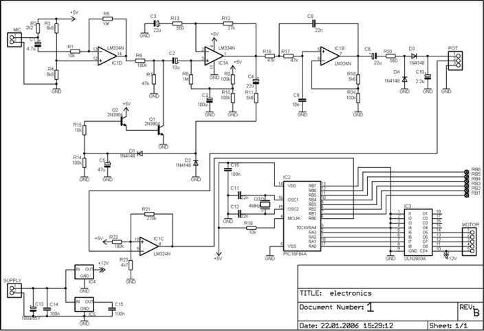
This is an early picture of my discolight effect. Because of the AGC circuit, there's no need for potentiometers for sensitivity adjustment. I replaced them with trimmers. Now the microphone is on the control electronics because there's no need...

This schematic is directly sourced from the Altera ByteBlaster datasheet or manual, which provides comprehensive details regarding the connector's functionality and pin connections. It is advisable to review the datasheet available on their website or through a search engine...
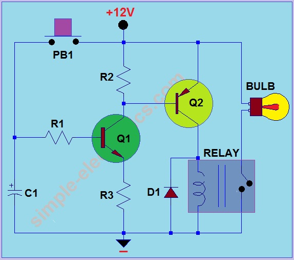
This circuit operates by activating a headlight when the push-button PB1 is pressed. The headlight remains illuminated for a predetermined duration, which can range from several seconds to minutes, before automatically turning off. When PB1 is engaged, capacitor C1...
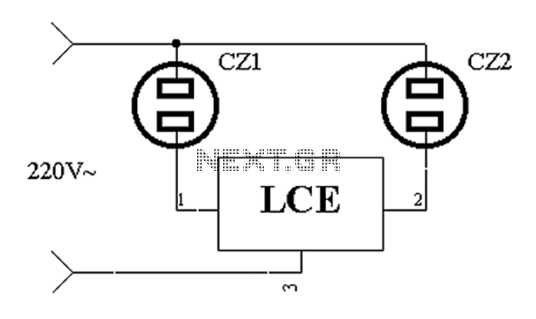
The application circuit operates the device as illustrated below. It is designed for cooling electrical equipment, typically utilizing a cooling fan to dissipate heat. The LCE employs a synchronous control socket on the device and its connections remain unchanged....
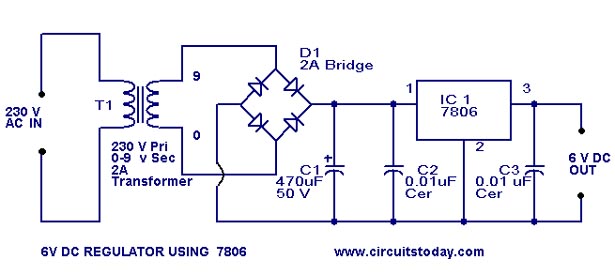
A simple 6-volt DC regulator circuit with a diagram and schematic using the 7806 IC, a positive voltage regulator. It serves as an elementary 6-volt, 1-ampere power supply circuit. The 7806 voltage regulator is a widely used integrated circuit that...