
Cooling fan control socket synchronous circuit diagram

The described circuit functions as an automatic cooling system for electrical devices, ensuring that heat generated during operation is effectively managed. The synchronous control mechanism enables seamless operation of the cooling fan in conjunction with the primary device.
The circuit typically includes a relay or a solid-state switch that is activated when the primary device is powered on. This relay connects the fan to the power supply, allowing it to operate concurrently with the electrical equipment. The power outlets CZ1 and CZ2 are strategically placed to facilitate easy connections for both the primary device and the cooling fan.
In terms of electrical specifications, the circuit may be designed to handle various voltage levels, depending on the requirements of the cooling fan and the primary electrical equipment. The use of appropriate fuses or circuit breakers is recommended to protect against overcurrent conditions that may arise during operation.
Additionally, the design can incorporate a thermal sensor that monitors the temperature of the electrical equipment. If the temperature exceeds a predetermined threshold, the sensor can trigger the relay to activate the fan even if the primary device is not powered on. This feature enhances the cooling efficiency and prolongs the lifespan of the electrical equipment by preventing overheating.
Overall, this application circuit presents a straightforward yet effective solution for managing heat in electrical devices, ensuring reliable operation and enhanced safety.Application circuit works the device as shown below. For cooling electrical equipment, usually with a cooling fan to drive heat. LCE made use synchronous control socket on the device and its line without any changes, as long as the power plug of electrical equipment into a power outlet CZ1, the fans plug into a power outlet CZ2 can be. When electrical equipment is powered fan will automatically start running when the power is off electrical equipment, electric fans also immediately stop working.
Related Circuits
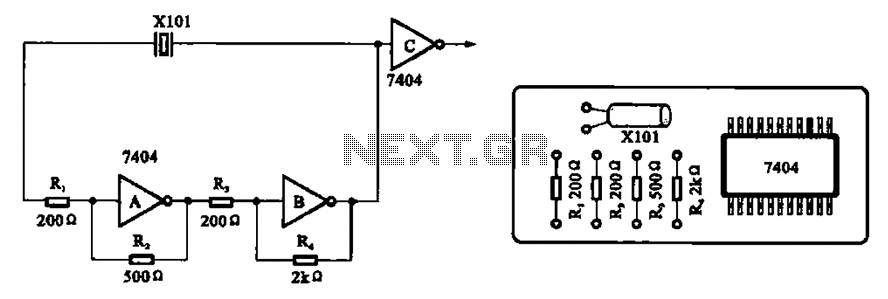
A clock oscillator is commonly utilized in digital signal processing circuits and microprocessor circuits. Digital signal transmission and signal processors necessitate a clock, which serves as the system's timing signal, while the data signal functions as a synchronization signal....
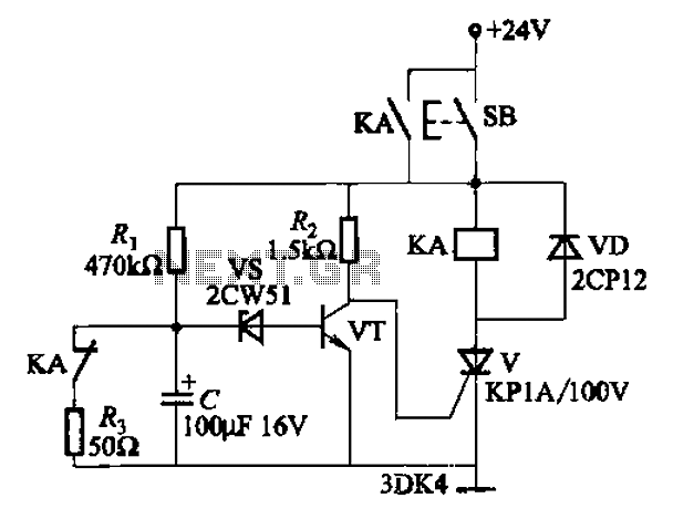
This circuit is a thyristor-based delay circuit known as a cut-off delay. It allows for a specified delay period after the thyristor is activated. The delay time of the circuit can be adjusted within 10 seconds by changing the...
When the microphone detects a loud sound, this circuit will activate the LED. The charge pump section includes a 100nF capacitor, a 10kΩ resistor, a signal diode, and a uF capacitor. The circuit operates by utilizing a microphone to sense...
The applet shows a simulation of Chua's circuit, plotting the voltage measured across C1 against the voltage measured across C2. This corresponds to the display on an X-Y oscilloscope with probes connected across these capacitors. The initial values of...
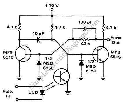
This is a flash-triggered (photo-driven) circuit that produces a pulse with a constant predetermined width. This circuit can be used to control any device. The flash-triggered circuit operates by utilizing a photodetector, which is typically a photodiode or phototransistor, to...
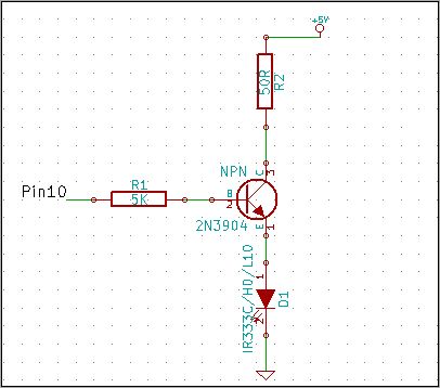
The 2N3904 is an NPN transistor. When observing the flat face of the transistor, the left lead is the Emitter (pin 1 in the schematic), the middle lead is the Base (pin 2 in the schematic), and the right...