
Lighting inverter circuit principle 6 ~ 8W fluorescent

The lighting inverter circuit for 6 to 8W fluorescent tubes operates by converting low DC voltage from a power source into a higher AC voltage necessary for the ignition and operation of the fluorescent lamp. The circuit typically comprises an oscillator, a transformer, and a rectifier. The oscillator generates a high-frequency signal that drives the transformer, which steps up the voltage to the required levels for the fluorescent tube.
The circuit parameters include a supply voltage of 6 to 12V, which is suitable for battery-powered applications or low-voltage power supplies. The current specification of 0.3 to 0.6A indicates the operational range of the circuit, ensuring that the inverter can handle the load without overheating or failing. The non-starting voltage of 45 to 65V is crucial, as it is the minimum voltage required across the lamp to initiate the ionization process within the gas-filled tube, allowing it to emit light.
The inverter circuit typically includes components such as resistors, capacitors, and inductors, which are carefully selected to ensure reliable operation. The oscillator may employ a simple transistor-based design or a more complex integrated circuit for improved efficiency and performance. The transformer must be rated to handle the required output voltage and current while maintaining minimal losses.
In summary, the lighting inverter circuit for 6 to 8W fluorescent tubes is a compact and efficient solution for low-voltage lighting applications, providing the necessary voltage and current to operate fluorescent lamps effectively. Proper attention to component selection and circuit design is essential to achieve optimal performance and reliability. As shown for the lighting inverter circuit principle 6 ~ 8W fluorescent. The circuit is suitable for lighting 6 ~ W fluorescent tube circuit parameters are marked in the figure . When using the W fluorescent general, the supply voltage is 6 ~ 12 V, current 0.3 ~ 0.6 A, non-starting voltage across the lamp during about 45 ~ 65V.
Related Circuits
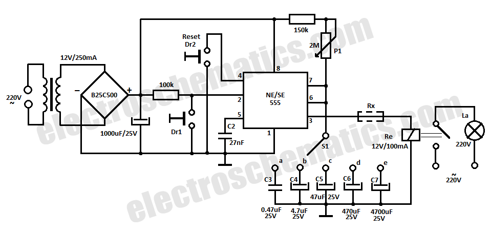
This time delay relay circuit is constructed using the NE/SE555 integrated circuit, manufactured by Intersil, which features a precision timer. The circuit exhibits stability against temperature variations. The NE/SE555 integrated circuit is a versatile timer used in various applications, including...
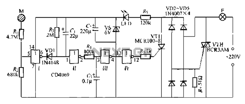
The CD4069 is a digital integrated circuit that utilizes boron to delay the activation of a light touch. It employs a j-wire connection force method and can directly replace a standard light switch without requiring changes to the existing...
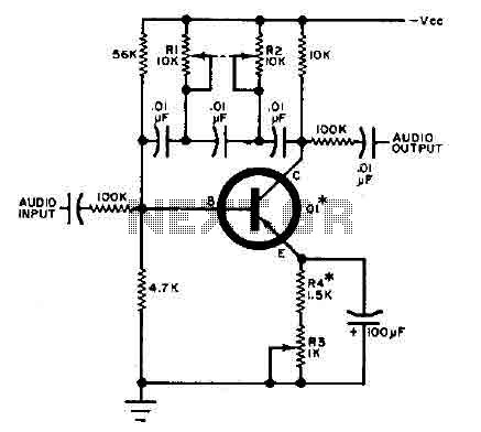
This circuit is designed for selective tuning adjustments between two closely spaced audio tones. The frequency of the circuit is determined by the selected capacitors and resistors in the feedback loop between the collector and base of transistor Q1....
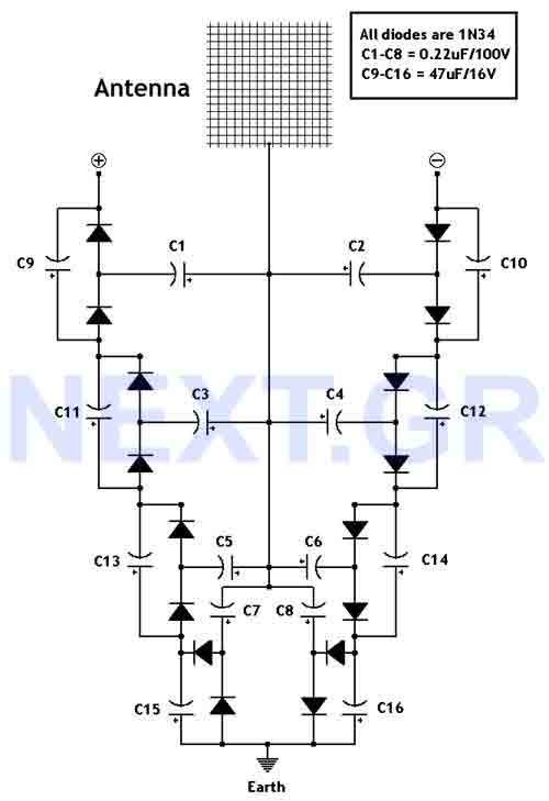
This circuit converts surrounding radio frequency waves to electric power. It can provide 40 Volts at 10 Watts indefinitely. The output power can be improved by adjusting the antenna. Placing the antenna near large metal objects increases power. The...

A field strength meter utilizing a biased Schottky detector employs a temperature-compensated Schottky diode within an amplified, untuned field strength indicator powered by two AA cells. This device indicates the relative field strength of RF fields ranging from a...
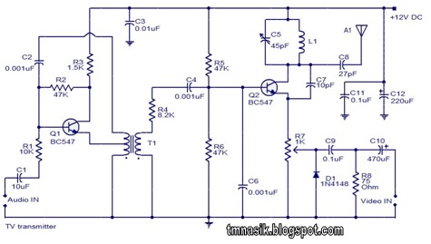
The TV transmitter circuit described utilizes UK standard 1 FM modulation for audio and PAL modulation for video. The audio signal intended for modulation is first amplified using transistor Q1 and its associated components. Transistor Q2 serves dual purposes:...