
Lilliput auto video switching for reversing camera

The Lilliput display is a versatile device often used in various applications, including professional video production and monitoring. The issue of automatic switching refers to the display's capability to detect input signals and switch between them without manual intervention. The presence of this feature in the secret menu suggests that it may be a hidden functionality that requires specific conditions or settings to be activated.
To address the automatic switching issue, it is essential to investigate the circuit design of the Lilliput display. The display typically utilizes a microcontroller to manage input signals and control the display output. This microcontroller can be programmed to monitor the input ports for active signals. When a signal is detected, the microcontroller should trigger a switch mechanism that routes the selected input to the display.
A typical schematic for such a system would include the following components:
1. **Microcontroller**: This serves as the central processing unit that interprets input signals and controls the switching mechanism. It is programmed to recognize active signals from various input ports.
2. **Input Ports**: These ports receive signals from different sources such as HDMI, VGA, or composite video. Each port should have signal conditioning circuitry to ensure that the signals are within acceptable voltage levels for processing.
3. **Switching Circuit**: This circuit is responsible for routing the selected input to the display. It may utilize analog switches or relays controlled by the microcontroller. The choice of switching technology can impact the response time and reliability of the switching action.
4. **Power Supply**: A stable power supply is crucial for the microcontroller and other components to function correctly. It should provide the necessary voltage and current levels as specified in the component datasheets.
5. **User Interface**: While the primary focus is on automatic switching, a user interface may be included to allow manual selection and configuration of settings, including enabling or disabling the automatic switching feature.
By ensuring that the microcontroller is properly programmed and that all components are functioning correctly, the automatic switching feature can be effectively utilized, enhancing the overall user experience with the Lilliput display.I have been reading a lot of posts about the Lilliput not being able to `auto switch` even though it is in the secret menu, so I decided to make a.. 🔗 External reference
Related Circuits
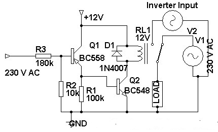
Three weeks ago, an inverter circuit diagram was introduced; however, the circuit did not include the AC to inverter switching part. Today, a 230 Volt AC to inverter switching circuit diagram is being presented. The circuit demonstrates inverter switching....
The circuit is capable of supplying either a trickle (50 mA) or high-current (1-A) charge. You can select either charging method or an automatic mode that will first trickle charge a battery if it is particularly low before switching...
The Camera Head (A2075) is a LWDAQ device designed to control and read a single ICX424 image sensor. The circuit includes a socket for soldering a 16-pin sensor directly and features a 12-way flex socket for connecting an auxiliary...
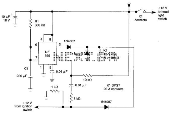
When the ignition switch is activated, relay K1 receives continuous power, allowing the headlights to be turned on. When the ignition is turned off, timer IC1 is activated, maintaining its power for a duration determined by resistor R1 and...
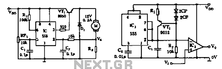
The circuit consists of a 555 motor automatic governor configuration. It includes flip-flops, a 555 timer, and a switching tube. A sampling circuit is formed by connecting R7 and the motor in series. RP1 is used to control the...
The AquaCont is an electronic system which permits to manage and to monitor most of the parameters of all the electric devices that can be found in an aquarium. The PIC18F4520 used to realize it combines a real-time clock...