
Composition 555 motor automatic governor circuit diagram

The described circuit utilizes the 555 timer in a motor control application, functioning as an automatic governor. The 555 timer is a versatile integrated circuit commonly used for timing and pulse generation. In this configuration, it operates in a feedback loop with a sampling circuit formed by the resistor R7 and the motor. The motor's operation is monitored through this sampling circuit, enabling the circuit to regulate the motor's speed based on predefined thresholds.
The flip-flops included in the circuit serve to maintain the state of the motor control, ensuring that the motor operates within the desired parameters. The switching tube acts as a control element that can either allow or cut off power to the motor, depending on the output from the 555 timer and the state of the flip-flops.
Adjustment of the trigger sensitivity is achieved through the variable resistor RP1. By altering the resistance, the voltage level at which the 555 timer triggers can be fine-tuned, allowing for precise control over the motor's response to changes in load or speed. This feature is particularly useful in applications where motor performance needs to be optimized for varying operational conditions.
Overall, this automatic governor circuit exemplifies an effective method for managing motor speed and performance, leveraging the capabilities of the 555 timer, flip-flops, and additional components to create a responsive and adjustable control system. As shown is composed of 555 motor automatic governor circuit. The circuit composed of flip-flops 555 and a switch tube. R7 and motor in series to form a sampling circuit. RP1 c ontrol 555 for adjusting the trigger level, ie adjust the trigger sensitivity.
Related Circuits
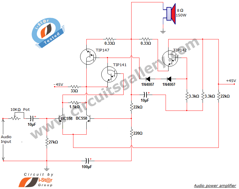
This document presents a new audio power amplifier schematic utilizing TIP darlington pair transistors. It is suitable for both home audio and car audio amplifiers. The TIP142 and TIP147 darlington pair transistors create a push-pull high-power amplifier configuration, while...
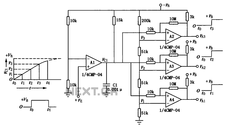
A multi-stage delay circuit is presented in this schematic. The operational amplifiers are configured as comparators. Operational amplifier A1 operates when the voltage at the inverting input exceeds + VE. As the voltage at the inverting input of operational...
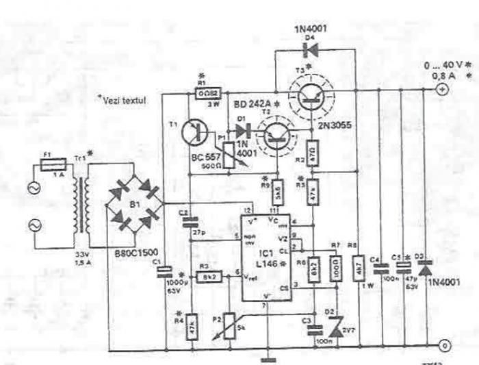
An adjustable laboratory power supply capable of providing an output voltage range from 0 to 60 volts can be constructed using the provided circuit diagram. This power supply can utilize the LM723 chip for lower voltage applications or, for...
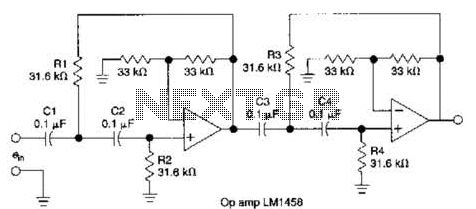
This circuit, which utilizes an LM1458 or a similar operational amplifier, functions as a fourth-order high-pass filter with a roll-off rate of 24 dB per octave. The resistor values Rx/R2 and RJRV can be adjusted to accommodate different cutoff...
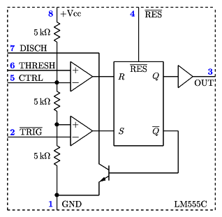
It is a typical Astable Multivibrator (AMV) setup. The capacitor charges through both resistors until it reaches 2/3 of Vcc, which is the level of the internal comparator. This triggers a flip-flop, activating the Discharge output (DIS). The capacitor...
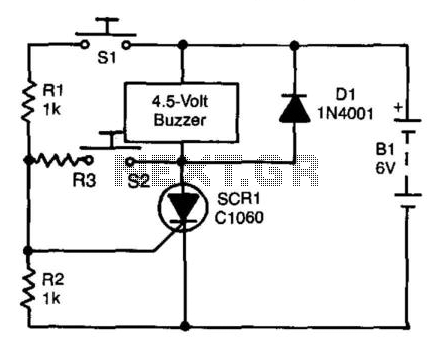
A self-interrupting device connected to a voltage source operates as a switch that continuously opens and closes; thus, the circuit does not latch in the conventional manner, allowing the alarm to function only while switch SI is closed. Due...