
Limit Temperature Buzzer

Part List
R1= 820 ohm D1= 5.6V 0.5W Zener K1= 6V 200 ohm Relay R2-3= 1Kohm D2-3= 1N4148 BZ1= Buzzer C1= 220uF 16V Q1-2= BC550C S1= 1x2 Switch TR1= 2.2Kohm Trimmer TH1= Thermistor 10Kohm at 25° C BATT= Battery 9V or external supply
The circuit functions as a temperature monitoring and alert system. The thermistor TH1 serves as the primary temperature sensing element. Its resistance decreases with increasing temperature, allowing the circuit to detect temperature changes effectively. The trimmer TR1 allows for fine-tuning of the threshold temperature at which the alarm will trigger.
Transistors Q1 and Q2 are configured in a Darlington pair to amplify the current from the thermistor, which ensures that even small changes in resistance due to temperature variations can drive the relay K1 effectively. When the temperature surpasses the set threshold, the Darlington pair turns on, energizing the relay, which can control various loads based on the application needs.
The relay K1 can switch higher power devices, making this circuit versatile for different applications such as controlling fans, heaters, or other temperature-sensitive equipment. The addition of a buzzer BZ provides an audible alert, while an optional LED can give a visual indication of the circuit's status.
Capacitor C1 stabilizes the power supply to the circuit, smoothing out any fluctuations that may occur, especially in battery-powered applications. The Zener diode D1 is included for voltage regulation, ensuring that the circuit operates within safe voltage limits.
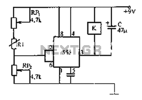
Overall, this temperature regulator circuit is a practical solution for monitoring and responding to temperature changes in various environments, providing both audible and visual alerts when the temperature exceeds the desired limits. Proper insulation and placement of the thermistor are crucial for accurate readings and reliable operation.The circuit is small regulatorof temperature, us warns for the increase of temperature. The control of temperature becomes from the thermistor TH1, that is negative factor. His resistance is altered between in the 10K in temperature 25° C and roughly in the 1K in their 94° C. The trimmer TR1 regulates the precise temperature in which the Q1-2, connected as darlington, conduct, making him relay K1 close also the buzzer BZ, sound.
The alarm is activated when the temperature becomes bigger than predetermining. The thermistor it should he is placed far from the remainder circuit, in order that this is not in danger from the temperature. The supply of circuit becomes from battery 9V, but if he is placed in constant place, then we can him supply with one power supply . In the contacts of relay we can connect what load we want, as a lamb, other circuit k.a. Also can is added a LED, if we want to have also optical clue of excitation. The regulation becomes sinking him thermistor TH1, in water which we know the temperature of (the contacts should are well insulate so that do not have short-circuit) and regulating him trimmer, until excited the circuit.
The cable that we connect the circuit with the TH1, should be plate. Part List R1= 820 ohm D1= 5.6V 0.5W Zener K1= 6V 200 ohm Relay R2-3= 1Kohm D2-3= 1N4148 BZ1= Buzzer C1= 220uF 16V Q1-2= BC550C S1= 1x2 Switch TR1= 2.2Kohm Trimmer TH1= Thermistor 10Kohm at 25° C BATT= Battery 9V or external supply 🔗 External reference
Related Circuits
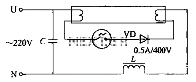
By incorporating a second pull tube into the circuit during the starter ionization phase, the positive half-cycle diode conduction results in an approximate DC current flow. This current is rectified, and due to the small ballast impedance, the instantaneous...
The LM134 is an effective temperature sensor due to its highly linear output characteristic. As a current output device, it remains unaffected by certain environmental factors. The LM134 is a three-terminal device that operates as a current source, providing a...
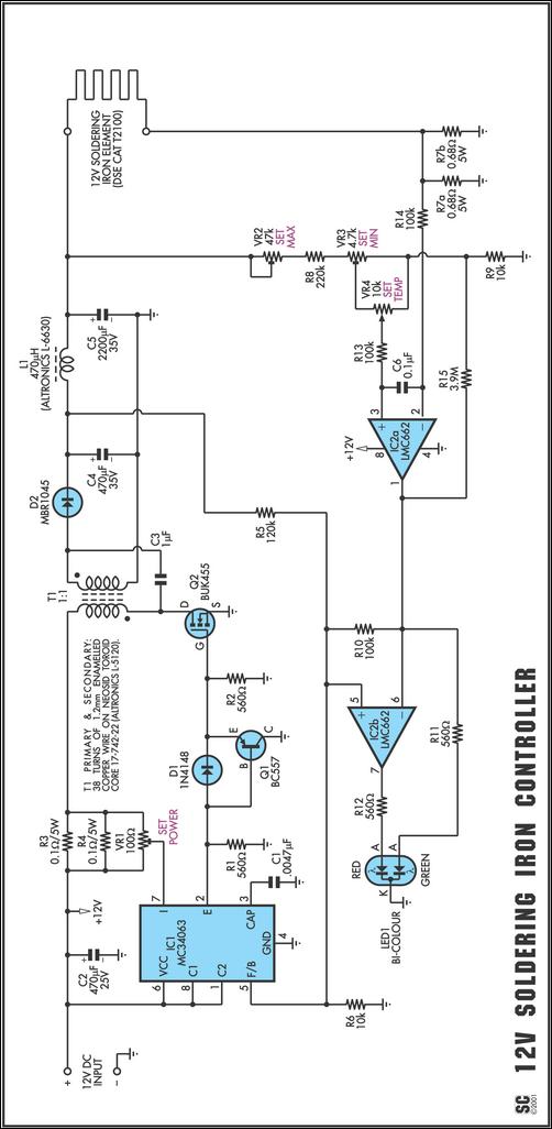
One reason commercial soldering stations are costly is that they typically use soldering irons equipped with built-in temperature sensors, like thermocouples. This circuit design eliminates the necessity for a specialized sensor by directly sensing the temperature of a soldering...
The 555 timer integrates both analog and digital functions within a scaled integrated device. Typically manufactured using a bipolar process, it is designated as the 555 timer, while the CMOS version is referred to as the 7555. In addition...
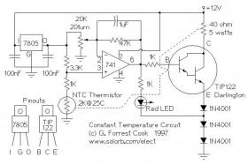
The following circuit illustrates the use of a 741 operational amplifier (op-amp) in a constant temperature control circuit diagram. It is designed to reduce the drift of a Ramsey FM10a. The circuit employs the 741 op-amp, which is a general-purpose...
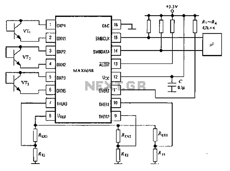
The circuit illustrated in the figure involves the MAX6698 maximum temperature sensor, which utilizes three transistors (VT1 to VT3) and three thermistors (RT1 to RT3). An internal reference voltage source is connected through resistors UREF REX1 to REX3, providing...