
line follower mobile robot

The project centers around the development of a line-following mobile robot, which utilizes a microcontroller as its central processing unit. The robot is designed to detect and follow a line on the ground, which is typically represented by a contrasting color to the surface. The essential components of the robot include the chassis, motors, wheels, sensors, and the microcontroller.
The chassis, repurposed from a remote-controlled vehicle, serves as the foundation for the assembly. It provides the necessary structure to house all other components. The motors, typically DC motors, are attached to the wheels and are responsible for propelling the robot forward and enabling it to turn. The control of these motors is managed by the microcontroller, which processes input from the sensors.
The sensors, often infrared or reflectance sensors, are positioned at the front of the robot. Their function is to detect the line by measuring the amount of reflected light. When the sensors identify the line, they send signals to the microcontroller, which then adjusts the motor speeds accordingly to keep the robot aligned with the line.
Programming the microcontroller involves writing a simple control algorithm that interprets the sensor data and determines the appropriate motor actions. This may include turning left or right, speeding up, or slowing down based on the robot's position relative to the line.
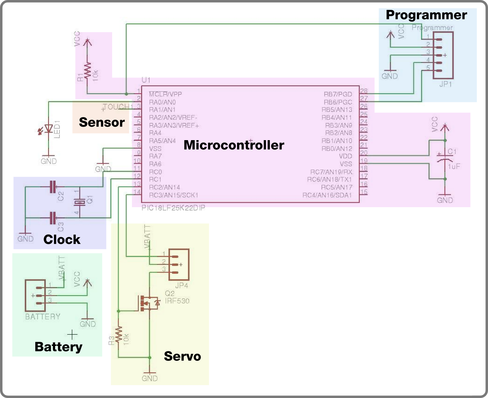
Overall, this project serves as an excellent introduction to robotics and microcontroller programming, offering practical experience in circuit design, soldering, and algorithm development. The challenges faced during assembly and programming will contribute to skill development in electronics and robotics.This is my first Microcontroller Hobby Project. He is ""Cruddy"" my line follower mobile robot. I named him Cruddy because he`s quite a mess on his structure. It is my first time on building a robot so expect that my soldering skills are not yet that good. The chassis was from a remote controlled.. 🔗 External reference
Related Circuits
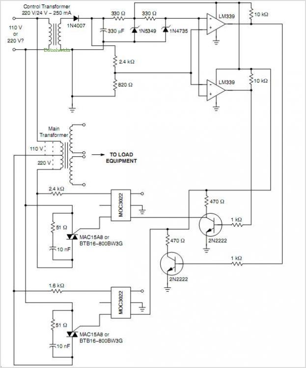
For the second build in the Make It Last Build Series, a robotic plant is being constructed. This week focuses on assembling the control circuit, which will be used in future weeks to animate the plant. The basic circuit...
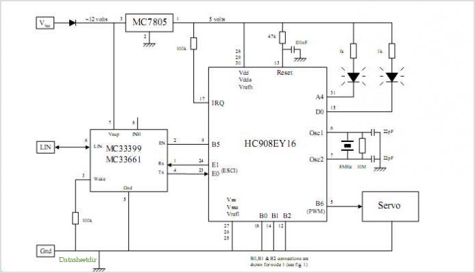
This application note outlines the implementation of a PSoC (Programmable System-on-Chip) device for controlling a Brushless DC (BLDC) windscreen wiper motor in automotive applications. The design incorporates LIN Bus 2.0 to facilitate the control of wiper operations. The document...
System Oscillator Crystal/Ceramic Oscillator. The following circuit combination of resistors, capacitors, and inductors depicts an equivalent circuit for a crystal or ceramic oscillator. The system oscillator, specifically a crystal or ceramic oscillator, utilizes a combination of passive components, including resistors,...

A single preset resistor is utilized across all measurement ranges, which simplifies the setup process. Diode clamping is incorporated to protect the meter from damage if the unknown resistor exceeds the selected range. When the meter is assembled, a...

This setup enables the allocation of pins on an mbed for a specified interface without the need to recompile the code. It utilizes a PS/2 keyboard as an input device and an LCD as an output device. The system...
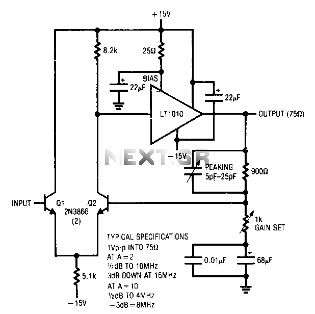
Q1 and Q2 create a differential stage that transitions into the LT1010. The capacitively terminated feedback divider provides a gain of 1, while permitting AC gains of up to 10. With a 20-ohm bias resistor, the circuit outputs 1...