
line follower robot

The line follower robot is designed to autonomously navigate along a designated path, typically marked by a contrasting line on the ground. The core of this project is the 8051 microcontroller, which serves as the brain of the robot, processing inputs from various sensors and controlling the motors accordingly.
The circuit diagram includes essential components such as the 8051 microcontroller, infrared (IR) sensors, motor driver circuits, and power supply units. The IR sensors are strategically placed on the robot's underside to detect the line. When the sensors detect the line, they send signals to the microcontroller, which processes this information and determines the appropriate motor actions to keep the robot on track.
The motor driver circuit is crucial for controlling the movement of the robot. It interfaces between the microcontroller and the motors, allowing for bidirectional control of the wheels. This enables the robot to make turns and adjustments as needed to stay aligned with the path.
Power supply considerations are also integral to the design. The circuit typically requires a stable DC power source to ensure reliable operation of the microcontroller and motors. Battery packs are commonly used to provide the necessary voltage and current.
In summary, the line follower robot project using the 8051 microcontroller is a practical application of embedded systems, showcasing the integration of sensors, microcontrollers, and motor control in a compact robotic platform. The project report includes a detailed explanation of the design, implementation, and testing phases, providing valuable insights for enthusiasts and learners in the field of robotics and automation.Line Follower Robot Project Using 8051 with circuit diagram is explained in this abstract. Download line follower or chaser robot full project report 🔗 External reference
Related Circuits
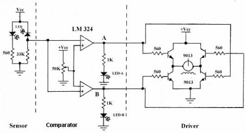
Line follower robots are commonly designed to follow a specific path on a track. Typically, these robots are controlled by microcontrollers; however, this article discusses a line follower robot designed without using a microcontroller. The assembly consists of three...
Circuit to close a relay when any phone extension is off-hook. Voltage at the gate of the MOSFET should be negative (1-3 volts) with respect to the source when phones are on-hook. Voltage at the gate should be positive...
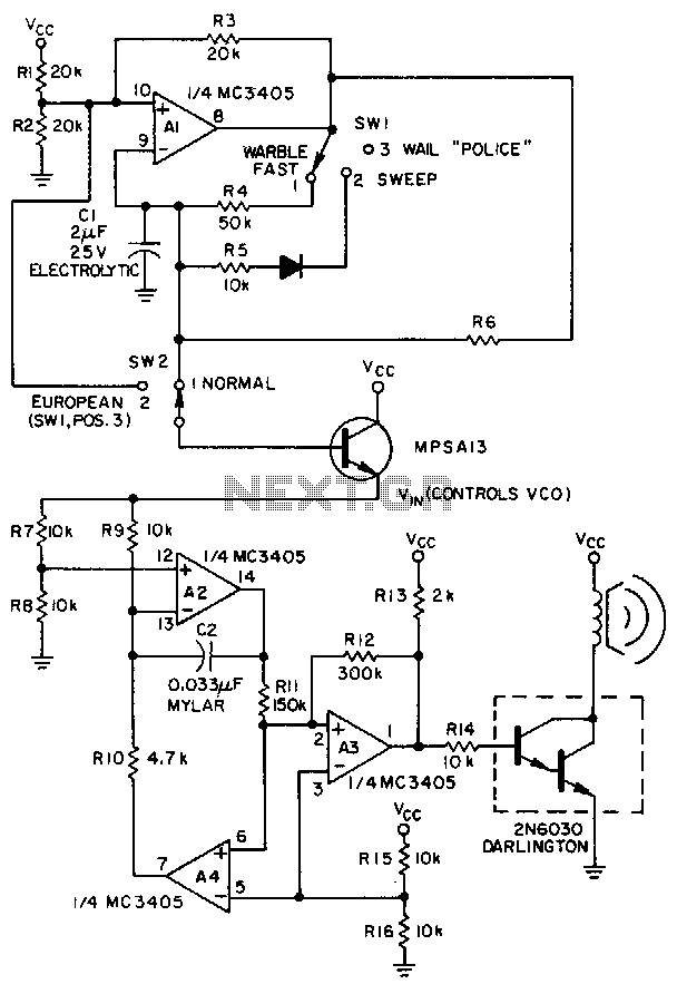
A low-frequency op-amp oscillator and a voltage-controlled oscillator (VCO), both configured using a single MC3405 dual op-amp and dual comparator, are the primary components in a siren circuit capable of producing various warbles and wails, or functioning as an...
A hybrid amplifier is being developed, utilizing an Aikido configuration for the voltage amplification stage (VAS) and an emitter-follower variation for the output stage (OPS). The hybrid amplifier design integrates two distinct amplification stages to achieve high performance and...
This design was developed to create a highly stable reference locked to a 10MHz source. With minor hardware modifications and entirely new firmware, an excellent GPS Disciplined Oscillator (GPSDO) was achieved using the same circuit board. The design effectively...
The circuit utilizes the principle that in an RL circuit, the pulse width across the inductor is proportional to the inductance. This circuit indirectly measures the inductance using a digital voltmeter (DVM). The measurement range is approximately 5 to...