
Linear Inductance Meter Circuit

The described circuit leverages the relationship between inductance and the time constant in an RL circuit to provide a measurement of inductance via a digital voltmeter. In this configuration, the inductor is subjected to a step voltage, causing a current to rise according to the time constant determined by the inductance (L) and the resistance (R) in the circuit. The pulse width observed across the inductor is directly related to the inductance value, allowing for an indirect measurement.
To implement this circuit, the following components are typically required: an inductor whose inductance is to be measured, a resistor to form the RL circuit, a switch to apply a voltage pulse, and a digital voltmeter to read the resultant voltage across the inductor. The resistor value can be selected to ensure that the time constant (τ = L/R) is within a range that can be accurately measured by the DVM.
The output voltage across the inductor during the pulse will vary with the inductance value. As the inductance increases, the pulse width will also increase, which can be calibrated to correspond to specific inductance values. The DVM is used to capture this voltage, which can then be translated into a corresponding inductance value within the specified range of 5 to 250 uH.
For accurate readings, it is essential to account for factors such as the resistance of the leads, the characteristics of the inductor, and the response time of the DVM. Calibration against known inductance standards can also enhance measurement precision. Overall, this circuit provides a practical means to measure inductance in a non-invasive manner, suitable for various applications in electronics and testing environments. Using the fact that in an RL circuit, the pulse width seen across the inductor is proportional to the inductance, this circuit reads this indirectly on a DVM. The range is about 5 to 250 uH.
Related Circuits
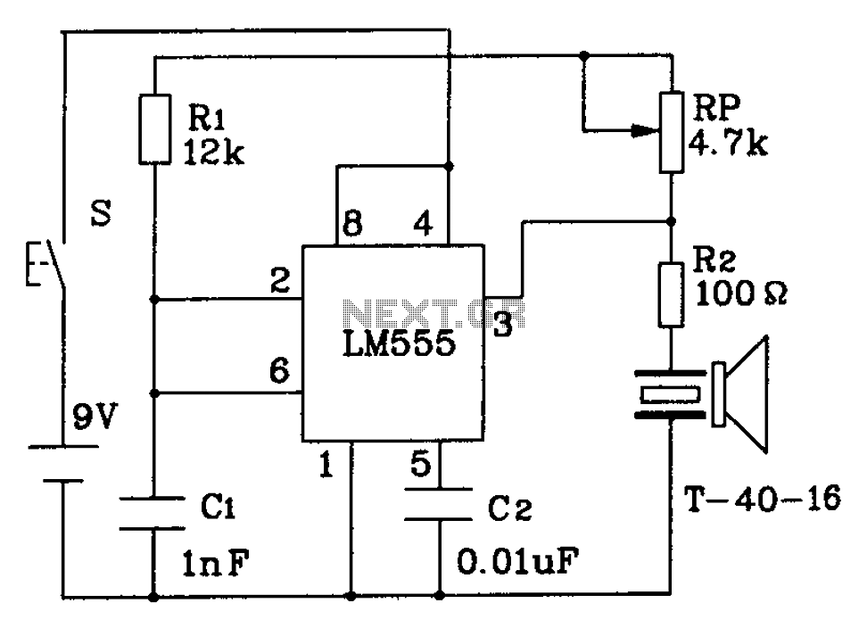
The circuit described is a 555 ultrasonic transmitter constructed to emit ultrasonic signals at a frequency of 40 kHz. It operates by generating oscillating pulse outputs from a 555 timer (specifically the T-40-16 model). The circuit is designed to...
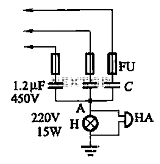
A 3-phase power system poses risks to electrical equipment, particularly asynchronous motors. To detect phase failure, an alarm circuit can be implemented. When the power supply is normal, the voltage at point A is approximately 0V, and no alarm...
To charge lead-acid batteries, a circuit can be utilized that consists of a current-limited power supply and a flyback converter topology. The circuit designed for charging lead-acid batteries incorporates a current-limited power supply alongside a flyback converter topology to...
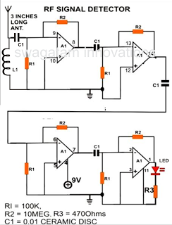
A simple electronic circuit project is presented that can be constructed by any school student for display at a school science fair. The proposed circuit is a high-gain operational amplifier (op-amp) amplifier designed to detect the slightest RF disturbances...
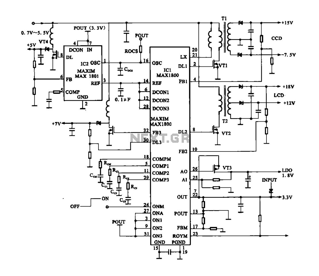
Digital Cameras - DV machine power supply circuit. This circuit utilizes the MAX1800 chip to manage the power supply for digital cameras and DV machines. Digital cameras are typically battery-operated and require low voltages ranging from 0.7 to 5.5...
This is the unedited version of the article "Improved Anode-Circuit Parasitic-Suppression For Modern Amplifier-Tubes," which was published on page 36 of the October 1988 issue of QST. A subsequent discussion on this topic appeared in the September and October...