
Line Following Robot Sensor

The line-following robot sensor operates using infrared light to detect the presence of surfaces or lines beneath the robot. The sensor typically consists of an infrared LED and a photodiode or phototransistor. The LED emits infrared light, which is reflected by the surface below. The photodiode or phototransistor receives the reflected light, and the intensity of this light is used to determine the proximity of the surface.
In a typical application, the sensor is mounted on the underside of the robot. When the robot approaches a line or edge, the amount of reflected infrared light changes, allowing the robot's control system to make real-time adjustments to its movement. This feedback loop enables the robot to follow lines or navigate around obstacles effectively.
The circuit design for this sensor can include additional components such as resistors to limit current through the LED, capacitors for noise filtering, and operational amplifiers to enhance the signal from the photodiode. The output can be connected to a microcontroller or a simple comparator circuit to determine the appropriate response based on the detected signal.
Overall, the line-following robot sensor is an essential component for autonomous robotics, providing reliable surface detection in a compact form factor, enabling efficient navigation and obstacle avoidance.This Line Following Robot sensor or surface scanner for robots is a very simple, stamp-sized, short range (5-10mm) Infrared proximity detector wired around.. 🔗 External reference
Related Circuits
This circuit explains alternate wireless switching using an ultrasonic sensor. The distance of the switching range should be more than 10 meters. The described circuit employs an ultrasonic sensor to facilitate wireless switching, allowing for the activation or deactivation of...

A sample robot was constructed using components from VCRs, with only the minimum necessary parts to create the simplest robot concept. Initially, the Nemesis microcontroller, produced by Kronos Robotics, was employed; however, it was not an optimal choice for...
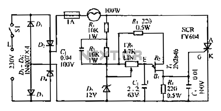
An AC voltage of 30V is rectified. The positive terminal is connected to a fuse and a 100W bulb, while the negative terminal is connected to a thyristor. A Zener diode provides a stable bias voltage. A variable resistor...
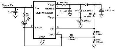
The ADM666A application note provides a detailed explanation of a low-cost battery charger circuit, including maximum output voltage, charge termination voltage calculation, battery voltage level monitoring, and circuit efficiency optimization. The ADM666A utilizes an NPN transistor and a P-channel...
A rain sensor alarm circuit is a useful device for alerting when rainfall occurs. The rain detector circuit presented is straightforward, utilizing only three components while maintaining high sensitivity to detect rain or moisture. The sensor can be constructed...

The sensitivity of the circuit can be adjusted using potentiometer P1 to avoid responding to ambient noise levels. Diodes D1 and D2 rectify the signal, while capacitor C4 provides smoothing. When the voltage across C4 exceeds 0.5 V, transistor...