
rain sensor alarm circuit

The rain sensor alarm circuit is designed to provide an effective warning system for rainfall detection. The circuit's simplicity is one of its key advantages, as it consists of only three primary components: the rain sensor, the BC547B transistor, and a buzzer. The rain sensor is typically created by placing two conductive strips in close proximity, which allows for the detection of moisture when raindrops bridge the gap between them. The recommended spacing of no more than one millimeter between the strips ensures that even small amounts of water can trigger the circuit.
The BC547B transistor operates in a switching mode in this application. When the sensor detects water, the resistance between the strips decreases, causing a small current to flow through the base of the transistor. This base current allows a larger current to flow from the collector to the emitter, effectively turning on the transistor. As a result, the 9V power supply is connected to the buzzer, which produces an audible alarm to alert the user of rainfall.
To enhance the circuit's reliability, it is advisable to include additional components such as resistors or diodes to protect the transistor from voltage spikes or to limit the current flowing through the buzzer. Moreover, the use of a waterproof enclosure for the sensor can increase its durability and effectiveness in outdoor environments. Overall, this rain sensor alarm circuit serves as a practical and efficient solution for monitoring rainfall, making it suitable for various applications such as garden irrigation systems, weather stations, or home automation systems.A rain sensor alarm circuit can be a very beneficial device for alerting when rainfall happens. The rain detector circuit shown here is very simple using only three components but is very sensitive to detect rain or moisture. The sensor part of the circuit can be easily made with verobaord or you can also make it in home by attaching thin metal st
rips on plastic or wood etc. The sensor can be made by several techniques, and performance of the circuit is also depends on the sensor. For better performance make sure to give no more than 1minimeter gap between the sensor strips. Working of the circuit is simple the transistor BC547B is working as a switch in this circuit when the water droplets fall on the sensor the transistor will become switched on and the 9V will start passing through the transistor which will activate the Buzzer.
🔗 External reference
Related Circuits

UART, GPS. This application note illustrates how to integrate a GPS module SC16C2552B into a navigation system using a Philips UART. With the rapid advancement of GPS (Global Positioning System) technologies, GPS is being increasingly utilized across various sectors....
Open and short circuit tests on a transformer are conducted to determine the equivalent circuit of the transformer, assess its voltage regulation, and evaluate its efficiency. The open circuit test is performed by applying the rated voltage to the primary...
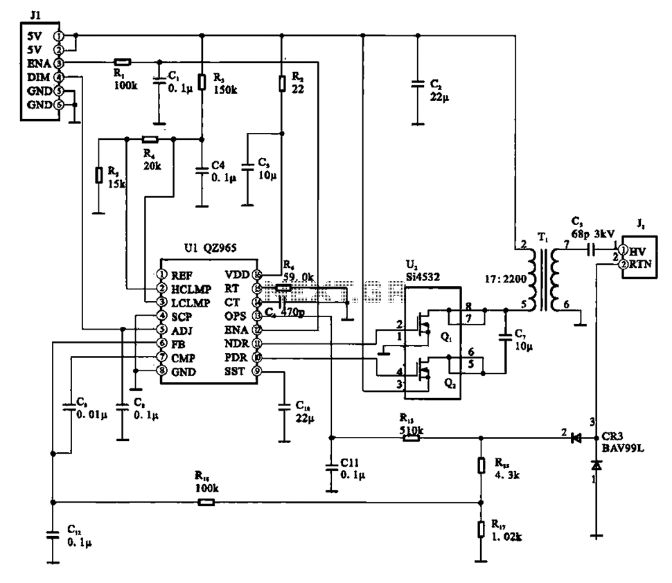
A typical liquid crystal display inverter circuit (OZ965) is primarily controlled by the OZ965 chip. It includes a driving field effect transistor (U2), a step-up transformer, the backlight socket, and associated circuitry. A 5V DC voltage is provided by...
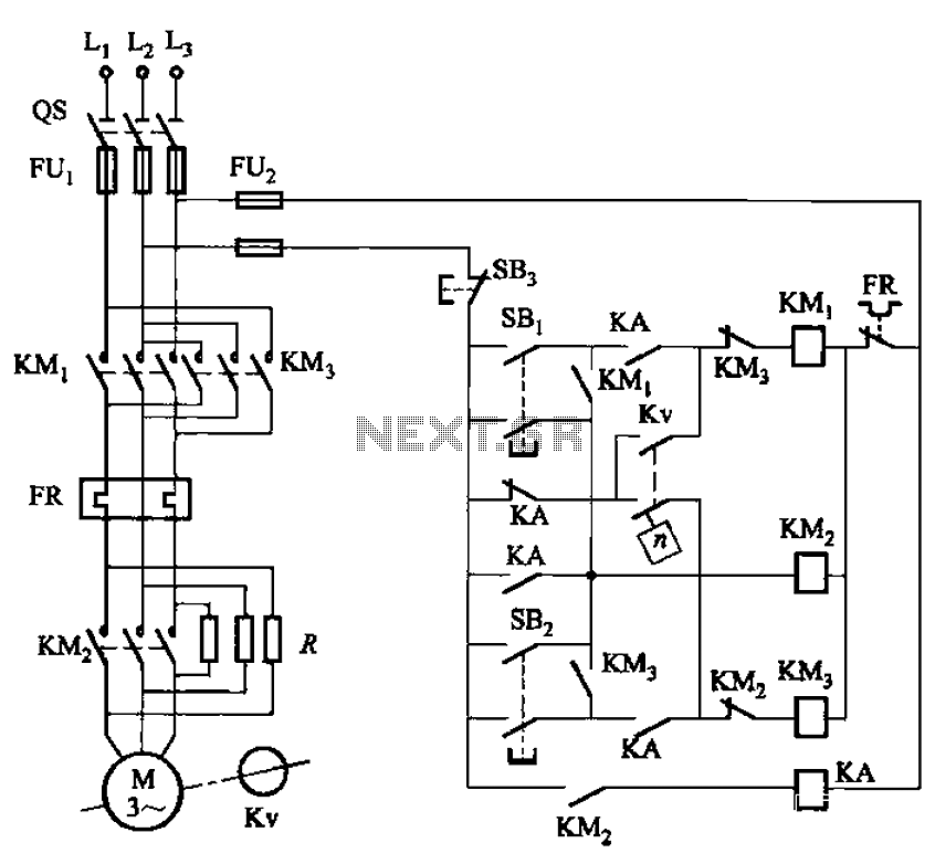
The circuit shown in Figure 3-129 is the C650-2 lathe brake control circuit, utilizing a speed control relay. The C650-2 lathe brake control circuit is designed to manage the braking mechanism of a lathe machine effectively. This circuit incorporates a...

The all-analog circuit presented controls the rate at which a miniature turbojet engine can be throttled. Increasing or decreasing the throttle too quickly on a miniature turbojet engine, or any jet engine, can lead to quick failure in flight,...
A switch that is controlled by its ambient temperature operates without human intervention, except during the assembly of the electronic thermostat. This thermally controlled switch has numerous practical applications. For instance, if the internal temperature of a computer rises...