
Line operated thyristor control time delay

The circuit operates by taking advantage of the characteristics of the CA3059 or CA3079, which are designed to provide a controlled zero-voltage switching mechanism. This feature allows for precise timing control when activating a triac, which is commonly used for AC load control applications.
In the circuit, the resistor (R) and capacitor (C) form an RC timing network that dictates the delay period. When the switch is closed, the capacitor begins to charge through the resistor. The time constant of the RC network is defined as τ = R × C, where τ represents the time it takes for the capacitor to charge to approximately 63.2% of the supply voltage. The voltage across the capacitor will rise exponentially until it reaches the threshold voltage necessary to trigger the triac.
Once the triac is triggered, it will remain in the 'on' state as long as there is sufficient current flowing through it, allowing for the control of AC loads without the need for mechanical switching. The precise values of R and C can be adjusted to modify the delay time, allowing for customization based on the specific requirements of the application.
This circuit design is particularly advantageous in applications where soft-start mechanisms are desired, minimizing inrush currents and extending the lifespan of connected components. Additionally, the use of zero-voltage switching reduces electromagnetic interference (EMI), making it suitable for sensitive electronic environments.
Overall, the combination of the CA3059 or CA3079 with a tailored RC timing network provides an effective solution for controlling the turn-on timing of triacs in various electronic applications.This circuit uses a CA3059 or CA3079 zero-voltage switch to control turn-on time of a triac. The delay between switch closure and turn-on is set by the values of R and C, as shown by the equation. 🔗 External reference
Related Circuits
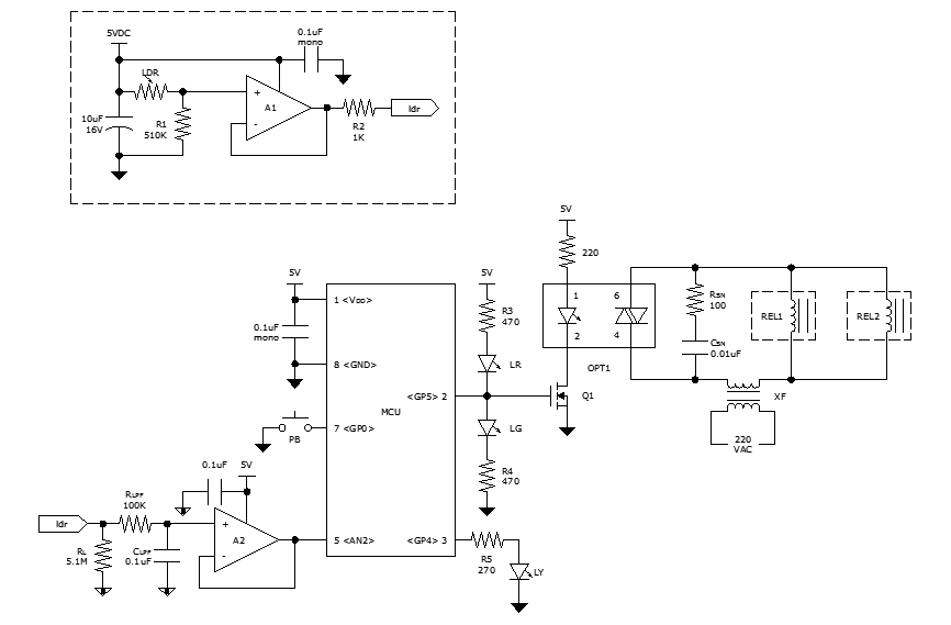
While discussing an all-linear automatic night light circuit, it was mentioned that an MCU-based Automatic Night Light Controller (ANLC) was being tested. The firmware has been tweaked since then. Recently, the sensor was installed outdoors and connected to control...
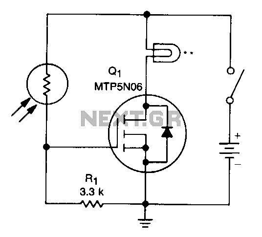
A school drama required lamps that automatically turned on and off in sync with the spotlights. The lamp switching system needed to be wireless, durable, reliable, simple, and cost-effective. With the stage and spotlights turned off, minimal light reaches...

The digital delay presented here is expected to be sufficient for most applications, and although the delay is fixed at 20ms, this is the most usable delay period. This is the equivalent of being about 7 metres away from...
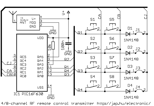
This is a general purpose remote control project with using programmable PIC microcontrollers. Schematics are shown for using infrared (RF) or radio (RF) media. If you are not familiar with microcontroller programming, you can use fixed encoder and decoder...
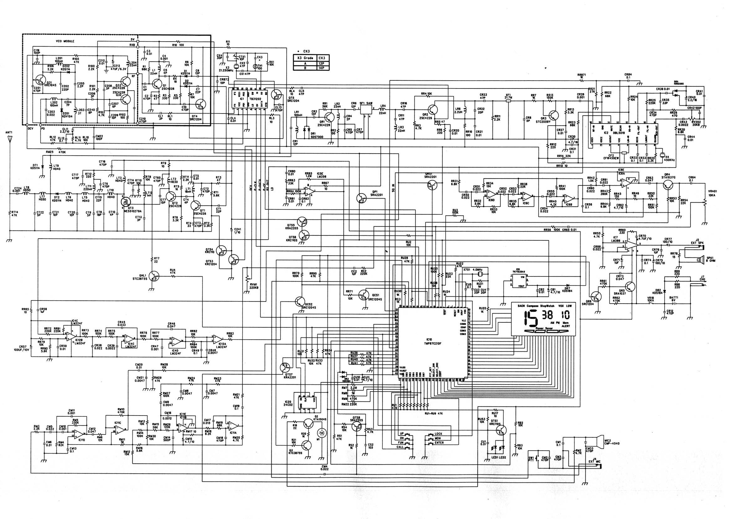
This is a simple hardware computer interface and Linux program that can be used to control the most commonly used buttons on any consumer Family Radio Service (FRS) or General Mobile Radio Service (GMRS) radio. There are 22 available...
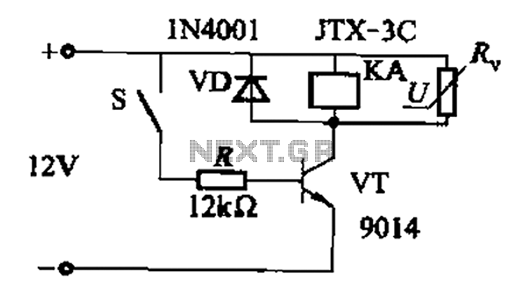
In a concrete circuit relay application, the transistor VT functions as a high-speed, high-voltage switch. The voltage requirement for switching is 5 to 10 times the rated voltage of the solenoid valve. The circuit is designed for a fast...