
Linux FRS Radio Control

The described hardware interface and software program facilitate control over a Cobra PR950DX FRS/GMRS radio, allowing users to manipulate essential functions via a computer. The interface operates by connecting the computer's parallel port to the radio's control buttons, which employ active-low logic. This means that pressing a button on the radio is achieved by grounding the corresponding control pin through the interface.
The 74LS244 buffer serves as an intermediary, ensuring that the computer's parallel port does not exceed its current sourcing capabilities, which could lead to hardware damage. The buffer IC is particularly advantageous when additional hardware components are integrated into the system. For instance, if the design is expanded to include more controls or indicators, the buffer can manage the increased load effectively.
The integration of diagnostic LEDs provides real-time feedback on the operational status of the interface, allowing users to observe the data being transmitted from the computer to the radio. This feature is particularly useful during troubleshooting or when verifying that commands are being sent correctly.
The audio injection capability allows for the integration of external audio sources, enhancing the radio's functionality. By removing the stock microphone and connecting an external audio feed, users can utilize the radio for various applications, such as relaying communications from other devices.
The power supply requirements are straightforward, with a +6 VDC input necessary for the operation of the radio and interface. The common ground between the radio and the computer is crucial for ensuring reliable communication and preventing signal interference.
Overall, this hardware interface and software program offer a practical solution for controlling FRS/GMRS radios, with potential applications in creating low-cost communication networks. The simplicity of the design allows for easy modifications and expansions, making it a versatile tool for electronics enthusiasts and developers.This is a simple hardware computer interface and Linux program which can be used to control the most commonly used buttons on any consumer Family Radio Service (FRS) or General Mobile Radio Service (GMRS) radio. There are 22 available FRS/GMRS frequencies in the 462-467 MHz band. Each channel is also capable of 38 "private" subchannels. The subchann els are the result of using different Continuous Tone Coded Squelch System (CTCSS) tones, also referred to as "PL" tones, for each channel. By remotely controlling the Mode, Up Arrow, and Push-to-Talk (PTT) buttons, you can control just about any feature or function of the radio.
This may be useful for anyone trying to build a store-and-forward "cellular" network using cheap FRS/GMRS radios (hint, hint). It`s possible to control other (or more) buttons with trivial hardware and software modifications. This particular example is built using a Cobra PR950DX FRS/GMRS radio (FCC ID: BBOPR950DXD) and a 74LS244 buffer/interface board.
The radio`s buttons are active-low (ground to enable) logic, so the hardware interface is quite simple. The computer software was written to run under the Linux operating system. It`s not the best software in the world, but that`s because I`m stupid. I have no idea how to do this under Windows - or why you`d want to. The computer-to-radio interface hardware consists of parts (except the 74LS244) which are available at your local Radio Shack.
The 74LS244 buffer IC is actually optional, as most computer parallel ports are limited to the amount of current they can source (output). This buffer will prevent any damage to your computer hardware should something short out, or if you need to control any additional hardware.
The diagnostic LEDs are also optional, but are helpful to verify what the computer is outputting, data wise, at a quick glance. Cobra PR950DX`s internal front view. The motor/vibrator and electret microphone have been removed. Inject your own audio (say from another radio) into the microphone jack on the top of the radio. The On/Off switch on the volume potentiometer is locked in the On position by soldering a jumper wire across its terminals.
Internal rear view. The PTT button has been removed. The solder pad with the arrow is the new PTT switch. The + and - on the lower left is for the +6 VDC power supply input. Test setup showing the computer interface board mounted internally. The RF output (via a short BNC jumper) is taken from the stock antenna connection. The BLACK numbers are the parallel port`s DB-25 pins. There should be a common ground between the radio and the computer. There are (optional) ferrite beads on the computer lines going into the 74LS244 buffer. 🔗 External reference
Related Circuits
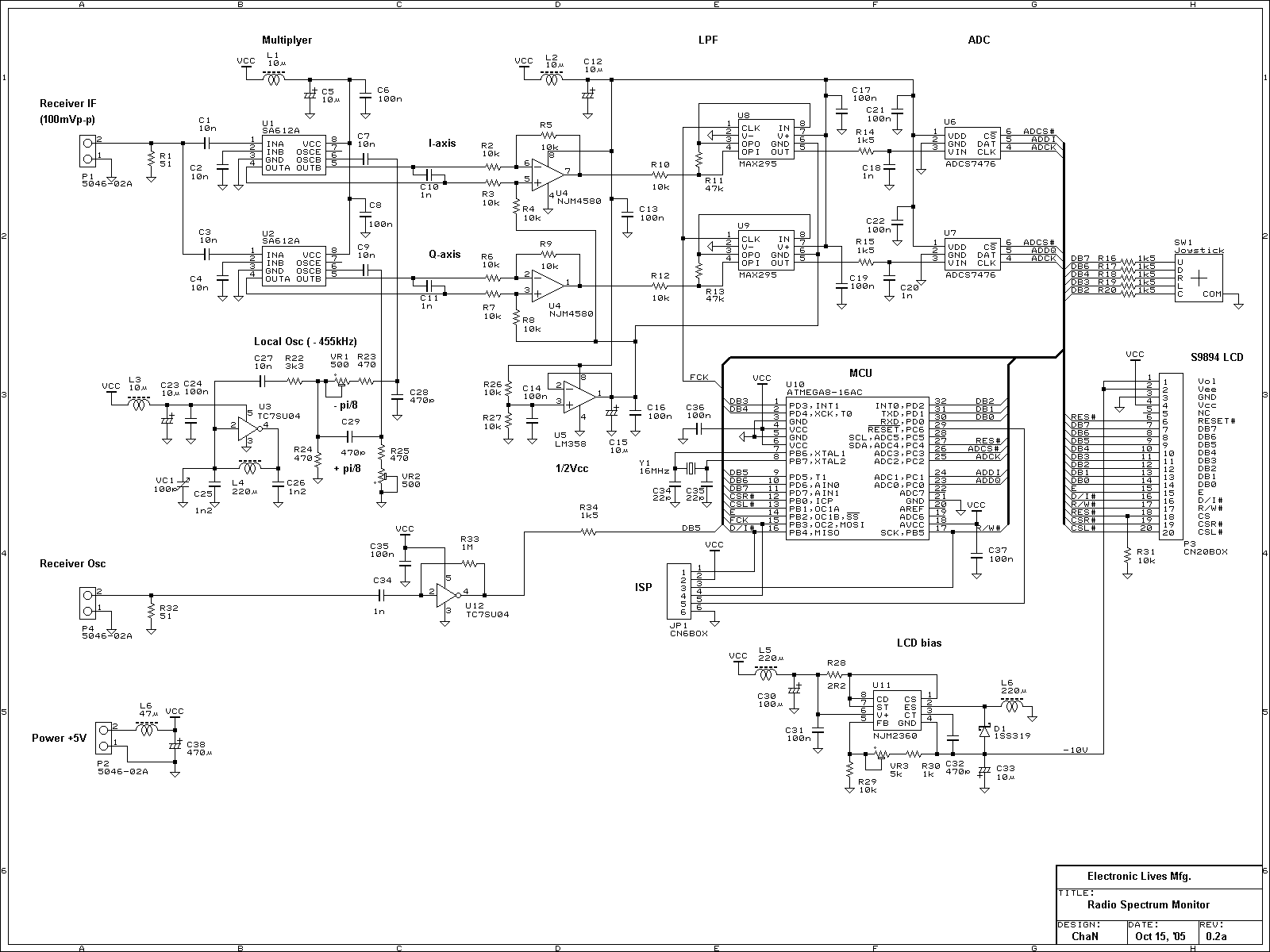
This is an experimental work to monitor a spectrum pattern of radio band, and is a continuous project from Audio Spectrum Monitor. To analyze the spectrum of an input signal, I chose an Atmel's AVR microcontroller used in Audio...
This circuit takes standard 0-10V control voltage (for example from analogue light controlling desk) and outputs a standard 1-2 ms RC servo motors control pulse. Power supply: 4-5V DC (same as for RC servo), consumes 15 mA of current....
The T7024 is a single-supply front-end integrated circuit (IC) specifically designed for applications within the 2.4 GHz to 2.5 GHz frequency band. This front-end configuration includes a Power Amplifier (PA), a Low-Noise Amplifier (LNA), and a switch driver for...
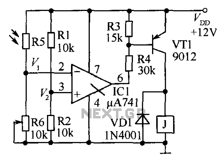
The circuit functions as a precision bright light control circuit, operating independently of power supply voltage and ambient temperature. Resistors R1, R2, R6, and the photosensitive resistor R5 form a two-arm Wheatstone bridge. The precision bright light control circuit utilizes...
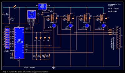
Stepper motors are widely used in applications such as process control, machine tools, and robotics. In particular, remote control of stepper motors is essential in robotics and process control. This document provides the circuit diagrams for both the transmitter...
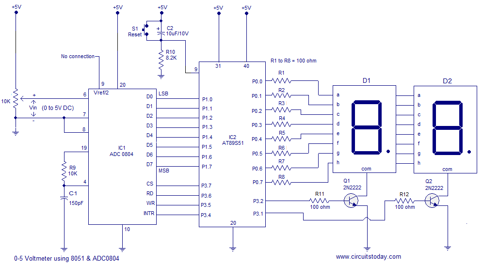
A simple 0-5 digital voltmeter utilizing the 8051 (AT89S51 microcontroller) is presented, accompanied by a circuit diagram and assembly language (ASM) code. This digital voltmeter is designed for straightforward voltage measurement. The circuit employs an AT89S51 microcontroller, which serves as...