
Linear Regulated Dual Polarity Power Supply

The dual polarity linear power supply is designed to provide both positive and negative voltage outputs, making it suitable for a variety of applications, including operational amplifiers, analog circuits, and other devices that require dual power rails. The specified voltage range of 1.2V to 35V allows for flexibility in powering different electronic components.
The primary components of the power supply include a step-down transformer, rectifier diodes, filter capacitors, voltage regulators, and necessary protection elements. The transformer steps down the AC voltage from the mains supply to a lower AC voltage suitable for rectification. Typically, a center-tapped transformer is used to facilitate dual polarity output, providing two equal voltage levels with respect to a common ground.
The rectification process is accomplished using a full-wave bridge rectifier configuration, which consists of four diodes arranged to convert the AC voltage into pulsating DC voltage. Following rectification, filter capacitors are employed to smooth out the pulsating DC, reducing ripple voltage and providing a more stable output.
To achieve the desired output voltage levels, linear voltage regulators are utilized. These regulators can be configured to provide the necessary positive and negative voltage outputs. Commonly used regulators include the LM7812 for positive voltage output and LM7912 for negative voltage output, though adjustable voltage regulators such as the LM317 can also be employed for greater versatility.
In addition to the main components, it is essential to incorporate protection features such as fuses, thermal shutdown, and over-voltage protection to enhance the reliability and safety of the power supply. Proper heat sinking should be considered for the voltage regulators to dissipate heat generated during operation, ensuring stable performance.
Overall, the dual polarity linear power supply serves as a critical component in electronic design, enabling the provision of stable and adjustable voltage levels necessary for the operation of various electronic devices.This document describes how to construct a dual polarity linear power supply which can be configured for any positive or negative voltage between 1.2-35V. A power supply is the fundamental building block of all but the simplest of electronic devices. It converts the alternating current (AC) from our wall outlets into direct current (DC) at some specified voltage.
🔗 External reference
Related Circuits
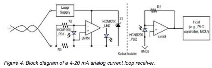
High linearity analog optocouplers offer the versatility needed to address a variety of analog isolation requirements. For high voltage applications, these optocouplers can effectively transmit analog signals between high voltage and low voltage areas without introducing distortion. This article...

A single preset resistor is utilized across all measurement ranges, which simplifies the setup process. Diode clamping is incorporated to protect the meter from damage if the unknown resistor exceeds the selected range. When the meter is assembled, a...
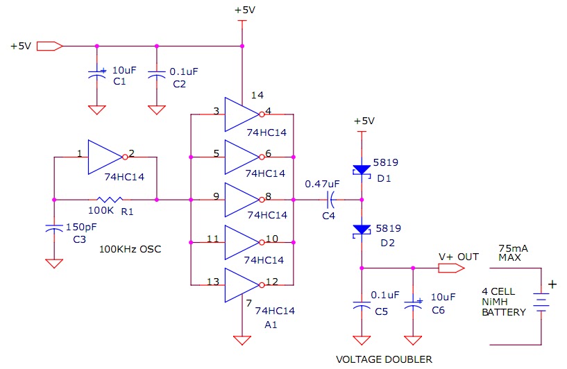
The circuit described will trickle charge a four-cell pack of AA or AAA NiMH batteries. It draws current from the +5V available from a USB connection and supplies approximately 70mA of current to the battery. This current level is...
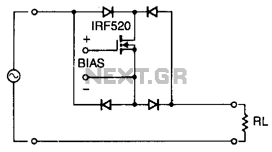
Utilizing four diodes in an array enables the use of a single MOSPOWER transistor for analog switching. The current flow is managed by maintaining the source-base connection of the MOSFET towards the load. It is essential to select diodes...
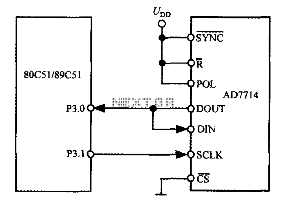
The 3-wire interface to the AD7714 can be utilized with various microcontrollers, including microcontrollers and microprocessors. This 3-wire serial interface is particularly suitable for isolation systems, allowing the use of optical couplers. The interface circuit between the AD7714 and...
The regulator board of the ES301 has been inspected, revealing that the PCB contacts of the current sensing resistors R42 and R43 are severely burned. There is a nearby group of resistors that also need to be replaced, but...