
Linear LTC4151 Voltage

The power monitoring device operates within a specified voltage range, making it versatile for various applications, particularly in automotive systems where voltage stability and accurate current measurement are critical during transient conditions. The integration of an I2C interface simplifies communication with microcontrollers, allowing for easy integration into existing systems.
The device utilizes a 5mOhm sense resistor, which is strategically placed in series with the load to accurately measure the current flowing through it. The small resistance value minimizes the voltage drop across the resistor, ensuring that the load receives nearly the full supply voltage while still enabling precise current monitoring. The current measurement is processed internally, and the results are communicated to the microcontroller via the I2C bus, which supports multiple devices on the same communication line, enhancing the flexibility of the system design.
In the provided schematic, the LTC4151 is highlighted as a key component, capable of handling high input voltages and providing robust performance in demanding environments. The device's ability to monitor up to 16A is particularly beneficial for applications such as automotive accessory sockets, where high current loads are common.
The use of a portable GPS unit as a demonstration tool exemplifies the practical application of this power monitoring device. By integrating the monitoring system with the GPS unit, real-time data on power consumption can be displayed or logged, providing valuable insights for optimizing power usage in automotive or portable electronic applications. This configuration not only enhances user experience but also contributes to energy efficiency in the design of modern electronic systems.This power monitor device provides accurate voltage and current monitoring of positive supply rail from 7V to 80V through a simple I2C interface, according to the datasheet. Such in automotive which has monitoring power in high transient environment, this device is suitablefor that purpose as well the high input voltage of the LTC4151.
You can see the above circuit schematic, it shows that the device monitoring up to 16A through a 5mOhms sense resistor at an accessory socket and feeding data via I2C microcontroller. And a portable GPS unit is used to illustrate the principle. 🔗 External reference
Related Circuits
The most effective way to understand space-charge tubes is to examine actual circuits. Review the online circuits provided below, and check if any older print articles are available from friends or personal collections. After familiarizing yourself with the material,...
The following circuit illustrates a low voltage power supply (PSU) for Nixie tubes utilizing a 555 Timer integrated circuit (IC). The coil used in this schematic is purchased from a store. The described circuit operates as a low voltage power...
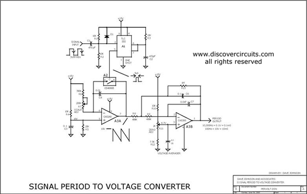
This circuit is designed to convert a square wave input signal into a voltage output. The voltage produced is proportional to the time interval between the edges (period) of the signal, rather than its frequency. The operational range of...
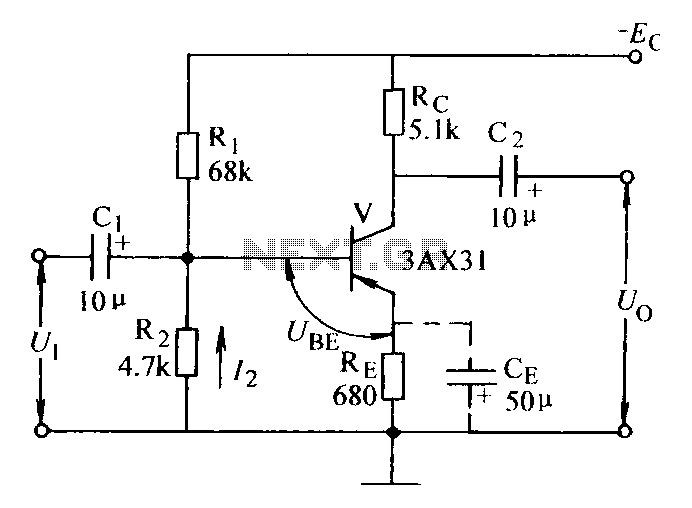
Current negative feedback voltage divider biased circuit diagram. The current negative feedback voltage divider biased circuit is a configuration commonly used in electronic amplifiers to stabilize the operating point and improve linearity. This circuit typically consists of an amplifier, a...
After constructing a Pulse Width Modulator for high-power LEDs, another LED modulator was developed for an optical transceiver. This project utilized a different approach, focusing solely on linear techniques for audio modulation. Similar to the PWM circuit, this circuit...
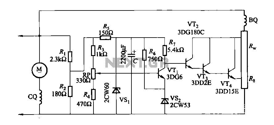
The DC generator automatic voltage regulator circuit is illustrated in Figure 7-53. This circuit is designed for a 40kW, 230V DC shunt complex machine, with a voltage change rate of up to 2.5 percent. In Figure 7-53, BQ represents...